Ceramics & Ceramic Processing
Materials Science Mastery
Atomic Structure & Quantum Foundations
Quantum mechanics, bonding, band theory, Fermi energy, phononsCrystal Structures, Defects & Diffusion
FCC/BCC/HCP, Miller indices, dislocations, phase diagrams, Fick's lawsMetals & Alloys
Iron-carbon diagram, steels, aluminum, titanium, superalloys, heat treatmentPolymers & Soft Materials
Polymer chemistry, thermoplastics, viscoelasticity, rheology, biopolymersCeramics, Glass & Composites
Oxide ceramics, toughening, fiber-reinforced composites, interfacial bondingMechanical Behavior & Testing
Stress-strain, hardness, fatigue, fracture toughness, nanoindentationFailure Analysis & Reliability Engineering
Fractography, corrosion, tribology, root cause analysisNanomaterials & Smart Materials
Nanotubes, graphene, piezoelectrics, shape memory alloys, self-healingMaterials Characterization Techniques
XRD, SEM, TEM, AFM, DSC, TGA, spectroscopyThermodynamics & Kinetics of Materials
Gibbs free energy, CALPHAD, phase stability, solidificationElectronic, Magnetic & Optical Materials
Semiconductors, photovoltaics, dielectrics, superconductorsBiomaterials
Implants, biocompatibility, tissue engineering, drug deliveryEnergy Materials
Battery materials, hydrogen storage, fuel cells, nuclear materialsComputational Materials Science
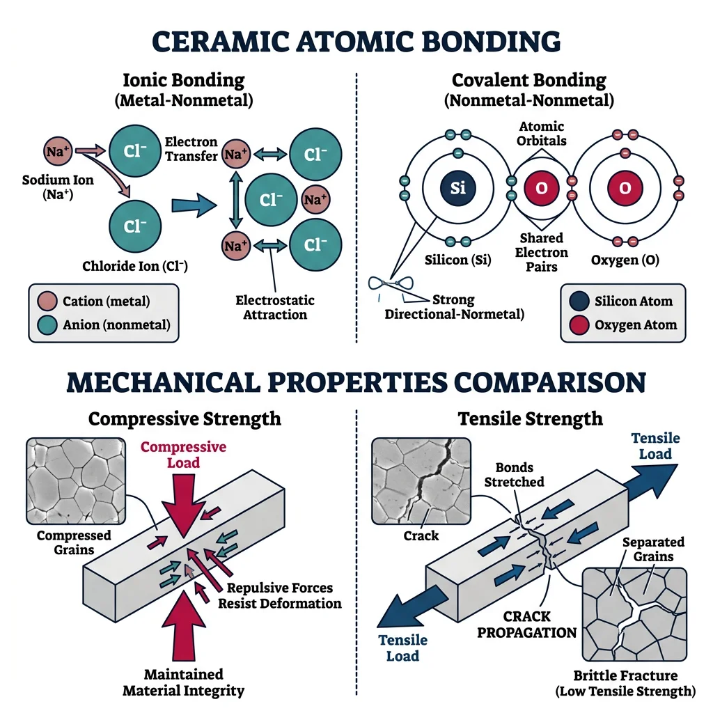
DFT, molecular dynamics, FEM, materials informatics, AICeramics are inorganic, non-metallic materials held together by ionic and/or covalent bonds. Unlike metals — where a "sea" of delocalized electrons allows atoms to slide past each other — ceramic bonds are directional and rigid. This gives ceramics extraordinary hardness, chemical inertness, and high melting points, but at a cost: they are inherently brittle.
Think of a brick wall: it can support enormous compressive loads — you can stack thousands of bricks without crushing the bottom ones. But try to bend or pull the wall apart, and it cracks easily. This is precisely how ceramics behave. Their compressive strength can exceed 2000 MPa (aluminum is ~300 MPa), yet their tensile strength may be only 50–200 MPa.
Oxide Ceramics
Oxide ceramics contain oxygen bonded to a metal. They are the most widely used ceramic family:
- Alumina (Al₂O₃) — Hardness ~9 on Mohs scale, melting point 2072°C. Used in cutting tools, spark plugs, hip implants, and electrical insulators. Annual global production exceeds 100 million tonnes.
- Zirconia (ZrO₂) — Exists in three crystal phases (monoclinic, tetragonal, cubic). Partially stabilized zirconia (PSZ) with yttria (Y₂O₃) is used for dental crowns, oxygen sensors, and thermal barrier coatings on jet engine blades.
- Silica (SiO₂) — The foundation of glasses and many traditional ceramics. Quartz (crystalline SiO₂) has piezoelectric properties used in watches and oscillators.
- Titania (TiO₂) — Photocatalytic properties enable self-cleaning surfaces and water purification. Also the primary white pigment in paints.
Non-Oxide Ceramics
Non-oxide ceramics are bonded primarily through covalent bonds, giving them even higher hardness and temperature resistance:
- Silicon Carbide (SiC) — Hardness ~9.5 Mohs, sublimes at 2830°C. Used in abrasives, armor plates, semiconductor substrates, and brake rotors in sports cars.
- Silicon Nitride (Si₃N₄) — Exceptional thermal shock resistance and fracture toughness (~6–8 MPa·√m). Used in turbocharger rotors, ball bearings, and cutting tools.
- Boron Nitride (BN) — Hexagonal BN is a lubricant (similar structure to graphite). Cubic BN (c-BN) is the second hardest material after diamond, used to machine hardened steels.
- Boron Carbide (B₄C) — Third hardest material known. Used in tank armor and nuclear reactor control rods (excellent neutron absorber).
Ceramic Processing: Powder → Forming → Sintering
Unlike metals that are cast from a melt, most ceramics are manufactured through a powder processing route because their melting points are too high for conventional casting:
- Powder Preparation — Raw materials are milled to fine particles (typically 0.1–10 μm). Particle size distribution controls final density and microstructure.
- Forming — Powders are shaped by die pressing, slip casting (pouring a slurry into a plaster mold), tape casting (for thin sheets), or injection molding.
- Sintering — The "green" body is heated to 50–80% of the melting point. Atoms diffuse across particle boundaries, eliminating porosity and forming a dense polycrystalline body. Typical sintering temperatures: Al₂O₃ at 1500–1700°C, SiC at 2000–2200°C.
import numpy as np
import matplotlib.pyplot as plt

# Comparing hardness and fracture toughness of ceramics
ceramics = ['Al₂O₃', 'ZrO₂\n(PSZ)', 'SiC', 'Si₃N₄', 'B₄C', 'BN\n(cubic)', 'WC', 'Glass']
hardness_GPa = [18, 12, 25, 15, 30, 48, 22, 6]        # Vickers hardness in GPa
toughness_MPa_sqrtm = [3.5, 8.0, 3.0, 6.5, 2.5, 3.5, 12.0, 0.7]  # K_IC

fig, ax1 = plt.subplots(figsize=(10, 6))

x = np.arange(len(ceramics))
width = 0.35

bars1 = ax1.bar(x - width/2, hardness_GPa, width, label='Hardness (GPa)',
                color='#3B9797', edgecolor='white')
ax2 = ax1.twinx()
bars2 = ax2.bar(x + width/2, toughness_MPa_sqrtm, width,
                label='Fracture Toughness (MPa·√m)', color='#BF092F',
                edgecolor='white')

ax1.set_xlabel('Ceramic Material', fontsize=12)
ax1.set_ylabel('Hardness (GPa)', color='#3B9797', fontsize=12)
ax2.set_ylabel('Fracture Toughness K_IC (MPa·√m)', color='#BF092F', fontsize=12)
ax1.set_xticks(x)
ax1.set_xticklabels(ceramics, fontsize=9)
ax1.set_title('Hardness vs Fracture Toughness — The Ceramic Trade-Off', fontsize=14)

lines1, labels1 = ax1.get_legend_handles_labels()
lines2, labels2 = ax2.get_legend_handles_labels()
ax1.legend(lines1 + lines2, labels1 + labels2, loc='upper right')
plt.tight_layout()
plt.show()

print("Notice: Higher hardness generally means LOWER toughness.")
print("ZrO₂ (PSZ) is the exception — transformation toughening gives it both.")
Zirconia Dental Crowns — Engineering Beauty and Strength
Yttria-stabilized tetragonal zirconia polycrystal (Y-TZP) has revolutionized dentistry. With a flexural strength of 900–1200 MPa (vs. 100–300 MPa for traditional porcelain), zirconia crowns combine the aesthetics of natural teeth with the strength to withstand years of biting forces.
The secret lies in transformation toughening: when a crack tries to propagate through Y-TZP, tetragonal ZrO₂ grains near the crack tip transform to the monoclinic phase, expanding ~4% in volume. This compressive stress at the crack tip effectively "squeezes" the crack shut, requiring more energy to propagate further.
Modern CAD/CAM systems mill crowns from pre-sintered zirconia blocks in under 15 minutes. After sintering at 1500°C, the crown shrinks ~20% to its final size — a shrinkage that must be precisely pre-compensated in the milling software. Over 500 million zirconia restorations have been placed worldwide.
Toughening Mechanisms
The Achilles' heel of ceramics is brittleness. In metals, plastic deformation ahead of a crack tip absorbs energy and blunts the crack. Ceramics lack mobile dislocations — so cracks propagate catastrophically once they reach a critical size. Materials scientists have developed several ingenious strategies to improve ceramic toughness:
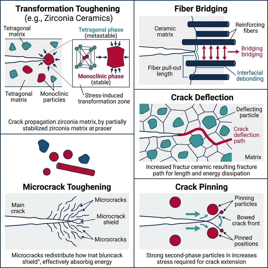
| Mechanism | How It Works | KIC Gain | Example |
|---|---|---|---|
| Transformation Toughening | Phase change at crack tip creates compressive stress | +5–10 MPa·√m | ZrO₂ (PSZ) |
| Fiber Bridging | Fibers span crack faces, resisting opening | +5–15 MPa·√m | SiC fiber in Al₂O₃ |
| Crack Deflection | Second phase particles force crack onto tortuous path | +2–5 MPa·√m | SiC whiskers in Al₂O₃ |
| Microcrack Toughening | Microcracks around particles absorb energy & dilate | +1–3 MPa·√m | ZrO₂ in Al₂O₃ |
| Crack Pinning | Hard particles anchor crack front, bowing it out | +1–4 MPa·√m | WC particles in Co |
Transformation Toughening in Detail
Pure ZrO₂ undergoes a tetragonal → monoclinic phase transformation at ~1170°C, accompanied by a 3–5% volume expansion. In bulk form, this expansion causes catastrophic cracking during cooling. The solution: add yttria (Y₂O₃) or ceria (CeO₂) to stabilize the tetragonal phase at room temperature.
When a crack approaches, the stress field at the crack tip triggers the transformation locally. The volume expansion generates compressive stresses that oppose crack opening — effectively increasing $K_{IC}$ from ~2 MPa·√m (unreinforced Al₂O₃) to ~8–12 MPa·√m (PSZ). This is called the process zone mechanism.
Weibull Statistics for Ceramic Reliability
Because ceramic failure is controlled by the largest flaw in the component, strength values are inherently scattered. Weibull statistics describe this probabilistic behavior:
$$P_f(\sigma) = 1 - \exp\left[-\left(\frac{\sigma}{\sigma_0}\right)^m\right]$$
Where $P_f$ is the probability of failure, $\sigma_0$ is the characteristic strength, and $m$ is the Weibull modulus. Higher $m$ means less scatter (more reliable). Metals typically have $m > 30$; ceramics range from $m = 5$ (poor quality) to $m = 20$ (high-quality Si₃N₄).
Thermal Shock Resistance
Pour boiling water into a cold glass jar and it shatters. The hot inner surface tries to expand but is constrained by the cold outer surface, creating tensile stress on the outside. Once this thermal stress exceeds the fracture strength, cracks propagate instantly. This is thermal shock.
The resistance to thermal shock is quantified by the thermal shock parameter:
$$R = \frac{\sigma_f (1 - \nu)}{\alpha E}$$
Where $\sigma_f$ is fracture strength, $\nu$ is Poisson's ratio, $\alpha$ is the coefficient of thermal expansion (CTE), and $E$ is elastic modulus. A higher $R$ means the material can withstand a larger sudden temperature change $\Delta T$ without cracking.
- Low CTE ($\alpha$) — Less expansion = less stress. Fused silica has $\alpha \approx 0.5 \times 10^{-6}$ /°C (vs. 9 × 10⁻⁶ for alumina).
- High thermal conductivity ($k$) — Rapid heat transfer reduces temperature gradients. SiC ($k \approx 120$ W/m·K) outperforms Al₂O₃ ($k \approx 30$ W/m·K).
- Low elastic modulus ($E$) — A more "forgiving" material develops lower stress for the same strain. Porous ceramics exploit this by intentionally reducing $E$.
import numpy as np
import matplotlib.pyplot as plt

# Thermal shock parameter R for various ceramics
materials = ['Fused\nSilica', 'Si₃N₄', 'SiC', 'Al₂O₃', 'Zirconia\n(PSZ)', 'Soda-Lime\nGlass', 'Porcelain']

# Material properties: sigma_f (MPa), nu, alpha (1e-6/°C), E (GPa)
props = {
    'Fused Silica':   {'sf': 110, 'nu': 0.17, 'alpha': 0.55, 'E': 73},
    'Si3N4':          {'sf': 700, 'nu': 0.27, 'alpha': 3.2,  'E': 310},
    'SiC':            {'sf': 400, 'nu': 0.17, 'alpha': 4.0,  'E': 410},
    'Al2O3':          {'sf': 300, 'nu': 0.22, 'alpha': 8.0,  'E': 380},
    'ZrO2_PSZ':       {'sf': 800, 'nu': 0.31, 'alpha': 10.5, 'E': 205},
    'Soda_Lime_Glass':{'sf': 70,  'nu': 0.22, 'alpha': 9.0,  'E': 70},
    'Porcelain':      {'sf': 50,  'nu': 0.25, 'alpha': 6.0,  'E': 70},
}

R_values = []
for key in props:
    p = props[key]
    R = p['sf'] * (1 - p['nu']) / (p['alpha'] * p['E']) * 1e3  # scale for readability
    R_values.append(R)

colors = ['#3B9797', '#16476A', '#132440', '#BF092F', '#8B4513', '#666666', '#999999']

plt.figure(figsize=(10, 6))
bars = plt.bar(materials, R_values, color=colors, edgecolor='white', linewidth=1.5)
plt.ylabel('Thermal Shock Parameter R (relative units)', fontsize=12)
plt.title('Thermal Shock Resistance of Ceramic Materials', fontsize=14)
plt.xticks(fontsize=9)

for bar, val in zip(bars, R_values):
    plt.text(bar.get_x() + bar.get_width()/2., bar.get_height() + 2,
             f'{val:.0f}', ha='center', va='bottom', fontsize=9, fontweight='bold')

plt.tight_layout()
plt.show()

print("Fused silica has the HIGHEST thermal shock resistance")
print("due to its extremely low CTE (0.55 × 10⁻⁶/°C).")
print("This is why Pyrex (borosilicate, CTE ≈ 3.3) replaced soda-lime (CTE ≈ 9) for lab ware.")
Glass Science
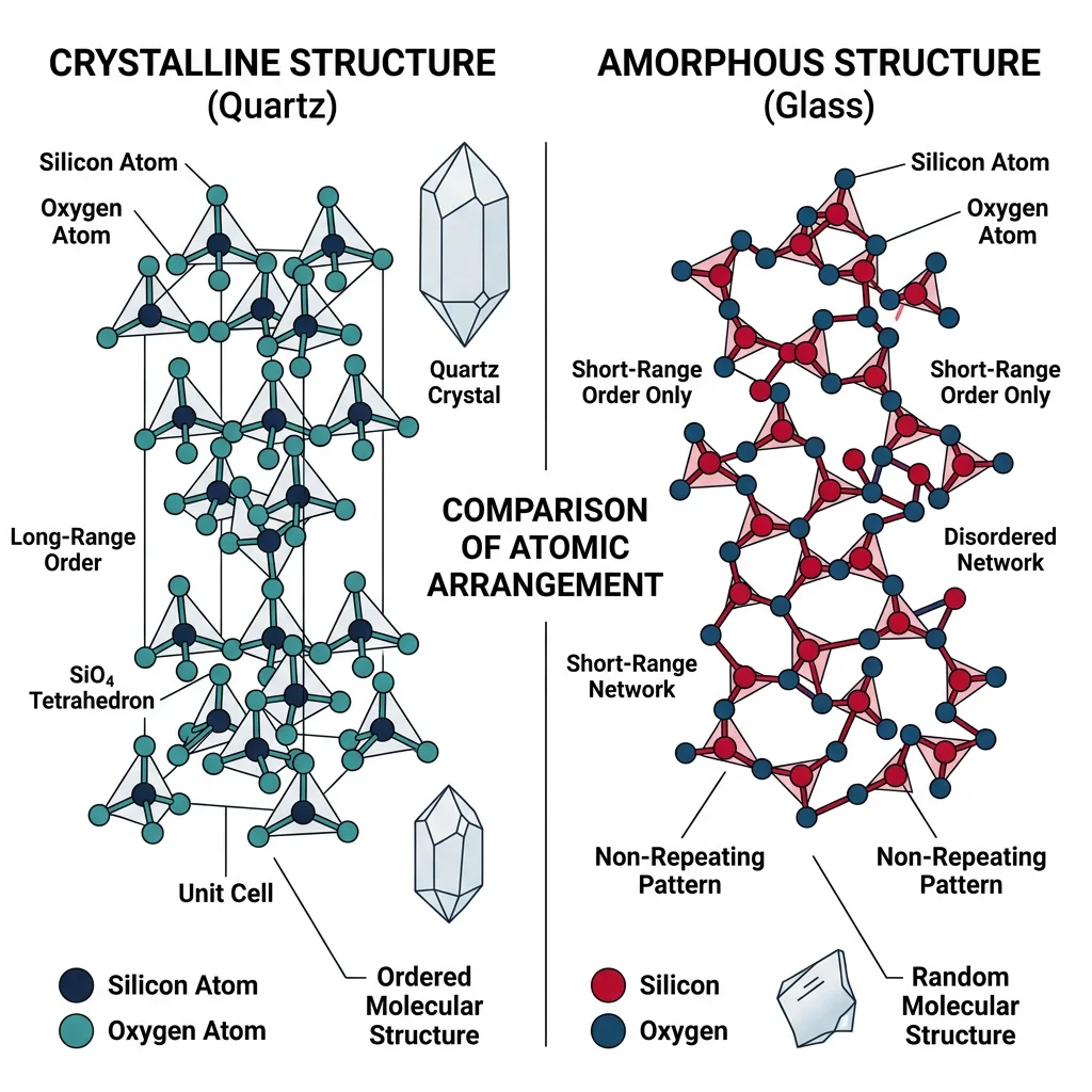
Is glass a solid or a liquid? This centuries-old question has a precise modern answer: glass is an amorphous solid — it has the rigidity and mechanical properties of a solid but lacks the long-range periodic atomic order of a crystal. The popular myth that medieval cathedral windows are thicker at the bottom because glass "flows" is false — the thickness variation is simply an artifact of the medieval crown glass manufacturing process.
Glass Composition — Formers, Modifiers, Intermediates
The structure of glass is understood through the Zachariasen rules (1932):
- Network formers (SiO₂, B₂O₃, P₂O₅) — Build the continuous random network. Each Si atom is tetrahedrally coordinated to 4 oxygen atoms, but the tetrahedra are arranged randomly, not in a repeating pattern.
- Network modifiers (Na₂O, CaO, K₂O) — Break Si–O–Si bridges, creating non-bridging oxygens. This lowers viscosity and $T_g$, making the glass easier to melt and form.
- Intermediates (Al₂O₃, PbO, ZnO) — Can act as either former or modifier depending on composition. Al₂O₃ strengthens the network; PbO increases refractive index (lead crystal).
Soda-lime glass — the world's most common glass (windows, bottles) — has a typical composition of ~72% SiO₂, ~14% Na₂O, ~10% CaO, and ~4% other oxides. Pure SiO₂ glass (fused silica) melts at ~1713°C; adding Na₂O drops the working temperature to ~1000°C, making large-scale manufacturing feasible.
The Float Glass Process
Invented by Alastair Pilkington in 1959, the float glass process revolutionized flat glass manufacturing. Molten glass at ~1100°C is poured onto a bath of molten tin (melting point 232°C). Glass floats on the denser tin, spreading into a perfectly flat, uniform sheet. As it moves along the tin bath, it cools and solidifies. The result: glass with optical-quality flatness on both sides, with no grinding or polishing required. Over 90% of the world's flat glass is now made this way.
Gorilla Glass — Chemically Strengthened for Smartphones
Corning's Gorilla Glass (an alkali-aluminosilicate) achieves its remarkable toughness through chemical strengthening via ion exchange. The glass is immersed in a molten potassium nitrate (KNO₃) bath at ~400°C for several hours. Larger K⁺ ions from the bath replace smaller Na⁺ ions in the glass surface, creating a compressive stress layer ~40–100 μm deep.
This compressive layer (700–1000 MPa) means that any surface flaw must first overcome the compressive pre-stress before it can open into a crack. Gorilla Glass Victus 2 (2023) can survive drops onto rough surfaces from 1 meter height. The technology protects over 8 billion devices worldwide.
The science is elegantly simple: stuff larger atoms into spaces designed for smaller ones, creating a "stressed skin" on the glass surface — essentially the glass equivalent of shot peening in metals.
Devitrification & Glass-Ceramics
Devitrification is the controlled crystallization of glass — intentionally nucleating and growing crystals within the amorphous matrix. The result is a glass-ceramic: a material that is typically 50–95% crystalline by volume, with crystals uniformly distributed in a residual glass phase.
The process involves two heat treatment steps:
- Nucleation (~700–800°C) — NGerators (TiO₂, ZrO₂, or P₂O₅ additives) create crystal seed sites throughout the glass.
- Crystal Growth (~900–1100°C) — Nuclei grow into tiny crystals (typically 0.1–1 μm), small enough to avoid light scattering (so the material can be transparent).
| Property | Soda-Lime Glass | Glass-Ceramic (LAS) | Why It Matters |
|---|---|---|---|
| CTE | 9 × 10⁻⁶/°C | ~0 (or negative!) | No thermal shock cracking |
| Max Use Temp | ~250°C | ~700°C | Cooktop surfaces |
| Strength | ~70 MPa | ~200 MPa | Mechanical loads |
| Transparency | Excellent | Transparent to opaque | Depends on crystal size |
| Manufacturing | Float glass, easy | Requires heat treatment | Higher cost |
Key applications of glass-ceramics:
- Ceran® cooktop surfaces — Lithium aluminosilicate (LAS) glass-ceramics with near-zero CTE survive rapid heating/cooling cycles from induction and radiant burners without cracking.
- Telescope mirrors — Zerodur® glass-ceramic (by Schott) has a CTE of ±0.05 × 10⁻⁶/°C, ensuring dimensional stability under temperature fluctuations. Used in the VLT (Very Large Telescope) in Chile.
- Dental restorations — Lithium disilicate (IPS e.max) glass-ceramics combine aesthetics with 400 MPa flexural strength for crowns and veneers.
Specialty & Optical Glass
Beyond commodity soda-lime glass, specialty formulations serve demanding applications:
- Borosilicate Glass (Pyrex®) — Replacing some SiO₂ with B₂O₃ drops the CTE to ~3.3 × 10⁻⁶/°C, giving good thermal shock resistance. Standard for laboratory glassware, bakeware, and telescope optics.
- Aluminosilicate Glass — Higher Al₂O₃ content increases strain point and chemical durability. Base composition for Gorilla Glass and aircraft windshields.
- Lead Glass (Crystal) — Adding PbO (24–35%) increases refractive index to ~1.7 (vs. 1.5 for soda-lime), producing brilliant light dispersion. EU restrictions now encourage lead-free alternatives using BaO or La₂O₃.
- Chalcogenide Glass — Based on S, Se, Te instead of oxygen. Transparent in the infrared (2–12 μm), used in thermal imaging lenses and fiber optics for CO₂ laser delivery.
Optical Fibers — Total Internal Reflection
Optical fibers exploit total internal reflection: a core of high-refractive-index glass (GeO₂-doped SiO₂, $n \approx 1.48$) is surrounded by a cladding of slightly lower index ($n \approx 1.46$). Light entering within the acceptance cone bounces along the fiber with minimal loss.
Modern single-mode fibers achieve attenuation of only 0.2 dB/km at 1550 nm wavelength — meaning a signal retains 1% of its power after 100 km. This extreme transparency requires silica of extraordinary purity: fewer than 1 part per billion of hydroxyl (OH⁻) ions.
Optical Fibers — Glass That Carries the Internet
Over 500 million kilometers of optical fiber have been installed worldwide — enough to stretch from Earth to Jupiter. A single fiber can carry 100+ Tbps using wavelength-division multiplexing (WDM), where different data streams travel on different colors of light simultaneously.
The manufacturing process is a marvel of precision: a preform rod (~1 m long, ~10 cm diameter) of ultra-pure SiO₂ is heated to ~2000°C and drawn into a fiber ~125 μm in diameter at speeds up to 60 m/s. A UV-curable polymer coating is applied in-line to protect the pristine glass surface from moisture and mechanical damage.
Fiber attenuation has reached the theoretical Rayleigh scattering limit for silica glass — we cannot make silica fibers any more transparent. Future improvements require hollow-core fibers (light travels in air, not glass) or novel materials.
Bioactive Glass — Bonding With Bone
Larry Hench's 45S5 Bioglass® (1969) was the first synthetic material that could chemically bond to living bone. Its composition (45% SiO₂, 24.5% Na₂O, 24.5% CaO, 6% P₂O₅) dissolves in body fluid and forms a hydroxyapatite layer — the same mineral that makes up bone and teeth. This layer is recognized by osteoblasts, which build new bone directly on the glass surface.
Modern bioactive glasses are used in bone grafts, dental applications, and wound healing (Bioglass particles release ions that stimulate angiogenesis and antibacterial activity).
Composite Materials
A composite material combines two or more distinct constituent materials to achieve properties that neither component can provide alone. The concept is ancient — the Egyptians used straw-reinforced mud bricks 3,000 years ago — but modern composites have revolutionized aerospace, automotive, sports, and infrastructure engineering.
Think of rebar in concrete: concrete handles compression beautifully but cracks under tension. Steel rebar handles tension but would buckle alone. Together, reinforced concrete spans bridges and holds up skyscrapers. This is the essence of composite design — combining complementary properties.
The Rule of Mixtures
For a simple aligned continuous-fiber composite loaded parallel to the fibers (the iso-strain condition), the composite modulus follows the Rule of Mixtures:
$$E_c = E_f V_f + E_m V_m = E_f V_f + E_m (1 - V_f)$$
Where $E_c$, $E_f$, $E_m$ are the moduli of composite, fiber, and matrix; $V_f$ and $V_m$ are volume fractions of fiber and matrix. This gives an upper bound on stiffness. For loading perpendicular to fibers (iso-stress):
$$\frac{1}{E_c} = \frac{V_f}{E_f} + \frac{V_m}{E_m}$$
This gives a lower bound. Real laminates with multiple ply angles fall between these bounds.
Fiber Types
- Glass fibers (E-glass, S-glass) — The workhorse. E-glass: $E = 72$ GPa, $\sigma_f = 3.4$ GPa. Cheap, good strength, poor stiffness. S-glass is 30% stronger. Used in boats, wind turbine blades, automotive panels.
- Carbon fibers (T300, T800, M60) — $E = 230$–$600$ GPa, $\sigma_f = 3.5$–$7.0$ GPa. Made by pyrolyzing polyacrylonitrile (PAN) at 1000–3000°C. "T" grades optimize tensile strength; "M" grades optimize modulus.
- Aramid fibers (Kevlar®) — $E = 70$–$180$ GPa, exceptional impact resistance. Used in body armor, tire reinforcement, and helicopter blades. Poor in compression (fibrillation).
- Basalt fibers — Made from volcanic basalt rock, $E \approx 90$ GPa. More sustainable alternative to glass fibers with better chemical resistance. Emerging for infrastructure applications.
Fiber Architecture
Fiber arrangement determines directional properties:
- Unidirectional (UD) — Maximum strength and stiffness in one direction. Anisotropic — weak in the transverse direction.
- Woven fabrics — Plain weave (0°/90° interlocking), twill weave (diagonal pattern), satin weave (smooth surface). Trade stiffness for multi-directional properties and drapability over complex shapes.
- Braided — Fibers interlaced at ±θ angles. Excellent for tubular structures (bicycle frames, rocket motor cases). Can achieve quasi-isotropic behavior.
- 3D textiles — Through-thickness fibers prevent delamination. Used in aerospace fan blades (LEAP engine) and thick structures requiring damage tolerance.
import numpy as np
import matplotlib.pyplot as plt

# Rule of Mixtures calculation for Carbon Fiber Reinforced Polymer (CFRP)
# Epoxy matrix + T300 carbon fibers

E_fiber = 230.0   # GPa (T300 carbon fiber modulus)
E_matrix = 3.5    # GPa (Epoxy matrix modulus)

V_f = np.linspace(0, 0.75, 100)  # Fiber volume fraction (0 to 75%)
V_m = 1 - V_f                     # Matrix volume fraction

# Upper bound (iso-strain, parallel to fibers)
E_parallel = E_fiber * V_f + E_matrix * V_m

# Lower bound (iso-stress, perpendicular to fibers)
E_perpendicular = 1.0 / (V_f / E_fiber + V_m / E_matrix)

plt.figure(figsize=(10, 6))
plt.plot(V_f * 100, E_parallel, 'b-', linewidth=2.5, label='Parallel (iso-strain) — Upper Bound')
plt.plot(V_f * 100, E_perpendicular, 'r-', linewidth=2.5, label='Perpendicular (iso-stress) — Lower Bound')
plt.fill_between(V_f * 100, E_perpendicular, E_parallel, alpha=0.15, color='green',
                 label='Accessible Stiffness Range')
plt.axvline(x=60, color='gray', linestyle='--', alpha=0.7, label='Typical CFRP ($V_f$ = 60%)')

plt.xlabel('Fiber Volume Fraction (%)', fontsize=12)
plt.ylabel('Composite Modulus (GPa)', fontsize=12)
plt.title('Rule of Mixtures — CFRP (T300/Epoxy)', fontsize=14)
plt.legend(fontsize=10)
plt.grid(True, alpha=0.3)
plt.xlim(0, 75)
plt.ylim(0, 180)
plt.tight_layout()
plt.show()

# Print typical CFRP properties at V_f = 60%
V_f_typical = 0.60
E_par = E_fiber * V_f_typical + E_matrix * (1 - V_f_typical)
E_perp = 1.0 / (V_f_typical / E_fiber + (1 - V_f_typical) / E_matrix)
print(f"At V_f = 60%:")
print(f"  Parallel modulus:      {E_par:.1f} GPa")
print(f"  Perpendicular modulus: {E_perp:.1f} GPa")
print(f"  Anisotropy ratio:      {E_par/E_perp:.1f}x")
print(f"\nFor comparison: Aluminum E = 70 GPa, Steel E = 210 GPa")
print(f"CFRP at 60% V_f matches steel's stiffness at 1/5 the density!")
The Boeing 787 — 50% Composite Airframe
The Boeing 787 Dreamliner was the first major commercial airliner with a 50% composite airframe by weight (vs. ~12% for the 777). The fuselage is made from carbon fiber reinforced polymer (CFRP) using automated fiber placement (AFP) — a robot-guided process that lays narrow tapes of pre-impregnated ("prepreg") carbon fiber onto a barrel-shaped mandrel.
The one-piece barrel fuselage eliminates ~1,500 aluminum sheets and ~40,000–50,000 fasteners per fuselage section. This saves ~20% weight compared to an equivalent aluminum structure. Weight savings translate directly to fuel efficiency: the 787 uses approximately 20% less fuel per passenger-mile than the 767 it replaced.
CFRP also eliminates fatigue and corrosion issues that plague aluminum airframes, allowing the cabin to be pressurized to a higher equivalent altitude (6,000 ft vs. 8,000 ft), increasing passenger comfort. Humidity can also be maintained at 16% (vs. 4% in aluminum aircraft) because composites don't corrode.
Matrix Materials & Classification
The matrix binds fibers together, transfers loads between fibers, protects fibers from environmental damage, and determines the maximum service temperature. Composites are classified by their matrix material:
Polymer Matrix Composites (PMCs)
The most widely used class (~95% of all structural composites). Subdivided into:
- Thermoset matrices
- Epoxy — The gold standard for aerospace. $T_g \approx 120$–$200$°C, excellent adhesion, low shrinkage, but brittle. Used in >70% of structural composites.
- Polyester — Cheap, fast cure, lower performance. Dominant in marine and automotive applications.
- Vinyl ester — Better chemical resistance than polyester. Used in chemical plant piping and tanks.
- Bismaleimide (BMI) — Higher temperature capability ($T_g \approx 280$°C). Used in military fighter aircraft (F-22, F-35).
- Thermoplastic matrices
- PEEK — $T_g = 143$°C, $T_m = 343$°C. Excellent toughness (10× epoxy), chemical resistance, weldable. Boeing 787 floor beams.
- PPS — Good chemical resistance, lower cost than PEEK. Automotive under-hood applications.
- PEKK — Similar performance to PEEK, better for additive manufacturing. Airbus A350 brackets.
Metal Matrix Composites (MMCs)
Aluminum, titanium, or magnesium reinforced with particles (SiC, Al₂O₃) or fibers. Key advantage: higher service temperature than PMCs and better transverse properties. Examples: SiC-reinforced Al for brake rotors (Porsche, Brembo), Al₂O₃ fiber-reinforced Al for pushrods in racing engines, B₄C/Al for neutron shielding.
Ceramic Matrix Composites (CMCs)
Discussed in detail in the Advanced Ceramics section. Key advantage: strength retention at 1200–1600°C. SiC/SiC composites for jet engine hot-section components.
- PMC (epoxy): max ~180°C — car bodies, wind turbines, sporting goods
- PMC (BMI/polyimide): max ~320°C — military aircraft, nacelles
- PMC (PEEK): max ~260°C — brackets, floor beams, weldable structures
- MMC (Al/SiC): max ~350°C — brake rotors, engine components
- CMC (SiC/SiC): max ~1300°C+ — jet engine turbine shrouds, hypersonics
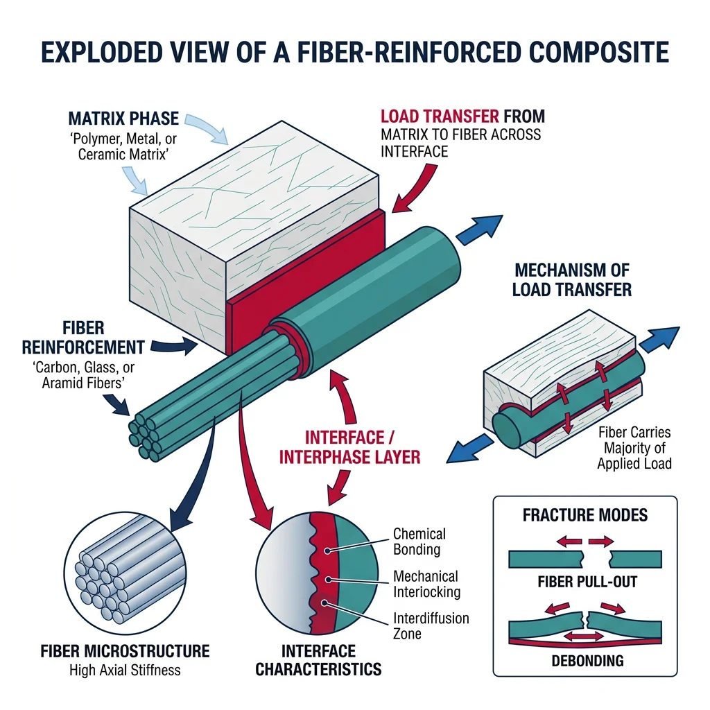
Interfacial Bonding & Load Transfer
The interface between fiber and matrix is the single most critical feature of any composite. Think of it as a handshake: if the grip is too weak, the fiber pulls out under load and contributes nothing. If the grip is too strong, cracks run straight through fibers, and the composite fails in a brittle manner with no warning. The ideal interface is strong enough to transfer load but weak enough to allow controlled energy absorption (fiber pullout, crack deflection).
Coupling Agents and Sizing
Glass fibers are coated with a silane coupling agent — a molecule with one end that bonds chemically to the SiO₂ glass surface and another end that bonds to the polymer matrix. Common silanes include aminopropyltriethoxysilane (APTES) for epoxy matrices. Without sizing, glass fiber/epoxy composites lose 30–50% of their wet strength because water displaces the weak physical bond at the interface.
Carbon fibers undergo oxidative surface treatment (electrolytic or thermal) to create oxygen-containing functional groups (–COOH, –OH, –C=O) that bond to epoxy. The fiber surface area increases from ~0.2 m²/g (untreated) to ~1.0 m²/g (treated).
Shear Lag Model (Cox, 1952)
The shear lag model describes how load transfers from the matrix to a discontinuous fiber through interfacial shear stress. At the fiber ends, the fiber carries zero load and the matrix carries all the stress. Moving inward, shear stress transfers load progressively to the fiber until the fiber reaches its full stress-carrying capacity. The critical fiber length $l_c$ is the minimum fiber length needed for the fiber to reach its full strength:
$$l_c = \frac{\sigma_f \cdot d}{2 \tau_i}$$
Where $\sigma_f$ is fiber tensile strength, $d$ is fiber diameter, and $\tau_i$ is interfacial shear strength. For carbon/epoxy: $l_c \approx 0.2$–$1.0$ mm. Fibers shorter than $l_c$ never reach full strength — they pull out. Fibers longer than $l_c$ can fracture.
- Fiber pullout — Interface fails in shear; fiber slides out. Energy absorbing (desirable in controlled amounts). Indicates weak interface.
- Debonding — Interface crack propagates along the fiber length. Often initiated by transverse loads or thermal mismatch stresses.
- Matrix cracking — Cracks in the matrix between fibers, especially under off-axis loading. First damage mode in most laminates.
- Delamination — Separation between plies. The most dangerous failure mode — can cause catastrophic structural failure with little visible surface damage.
- Fiber fracture — The fiber itself breaks. Indicates strong interface (good load transfer) but can lead to sudden failure cascades.
Advanced Ceramics & Frontier
Ceramic Matrix Composites (CMCs) represent the pinnacle of high-temperature structural materials. By embedding ceramic fibers (typically SiC) in a ceramic matrix (typically SiC), CMCs overcome the Achilles' heel of monolithic ceramics — catastrophic brittle failure — while retaining exceptional temperature capability up to 1300°C and beyond.
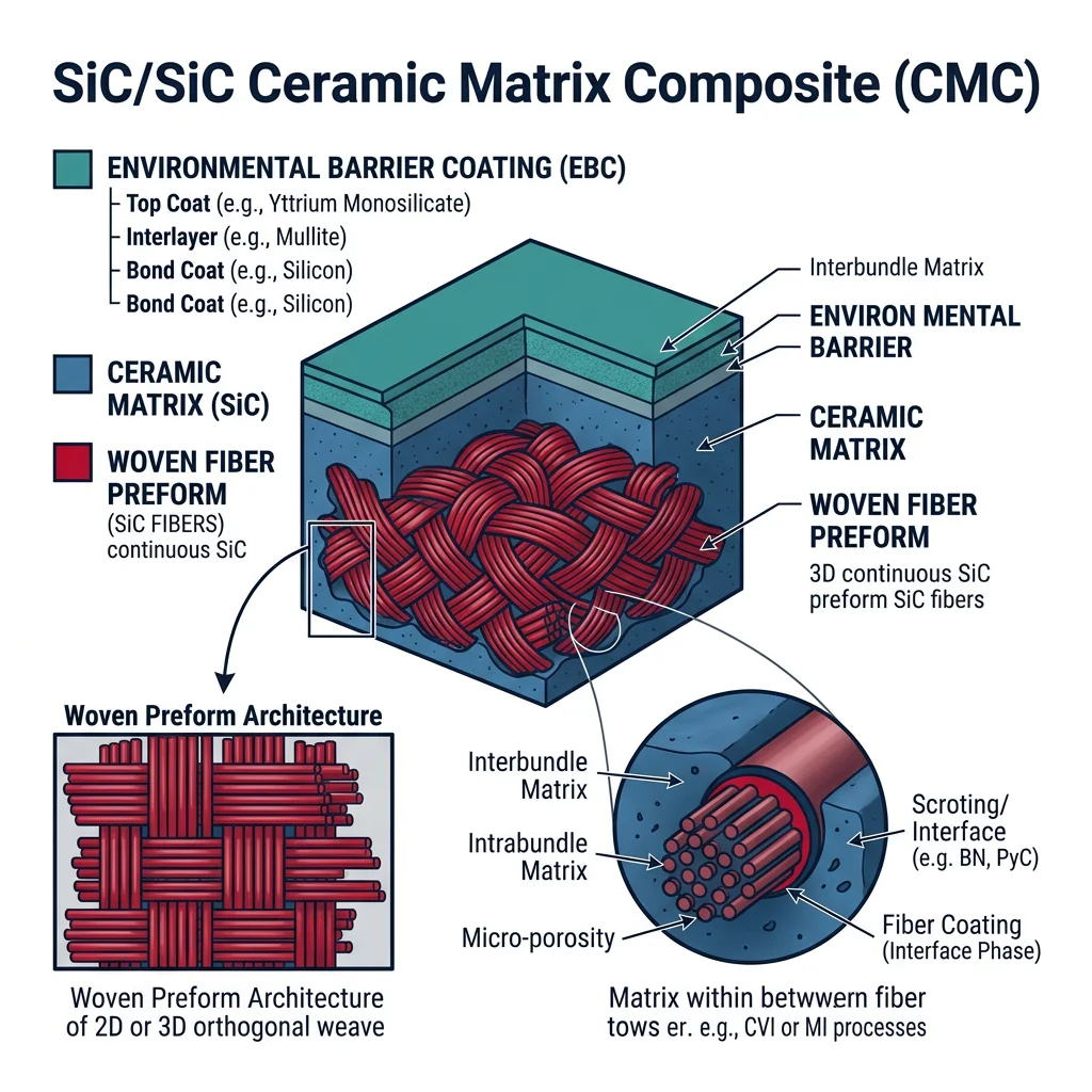
CMC Manufacturing Processes
Three primary routes exist for infiltrating a ceramic matrix into a fiber preform:
- Chemical Vapor Infiltration (CVI) — Gaseous precursors (e.g., methyltrichlorosilane for SiC) decompose and deposit a solid matrix within the fiber preform at 900–1100°C. Extremely slow (weeks to months) but produces high-purity, well-controlled microstructures. Dominant for aerospace CMCs.
- Polymer Infiltration and Pyrolysis (PIP) — A polymer precursor (polycarbosilane) is infiltrated into fibers, then pyrolyzed at 800–1200°C to convert the polymer to ceramic. Multiple cycles (6–10) are needed to achieve acceptable density. Faster than CVI but introduces more porosity.
- Melt Infiltration (MI) — Molten silicon is wicked into a partially-densified SiC preform. Fast (hours) and produces near-full density, but residual free silicon limits maximum temperature to ~1350°C.
LEAP Engine CMC Turbine Shrouds — Ceramics That Fly
GE Aviation's LEAP engine (powering the Boeing 737 MAX and Airbus A320neo) was the first commercial jet engine to use CMC components in the hot section. The CMC turbine shroud — the stationary ring surrounding the high-pressure turbine blades — operates at ~1300°C in combustion gas.
SiC/SiC CMC is one-third the density of the nickel superalloy it replaced (2.5 vs. 8.0 g/cm³), eliminating ~450 kg per aircraft. Lighter shrouds also require less cooling air — air that can instead be used for combustion, improving fuel efficiency by 15% compared to the predecessor CFM56 engine.
The CMC shrouds are manufactured at GE's dedicated facility in Asheville, North Carolina, using melt infiltration. Each shroud is a woven SiC fiber preform infiltrated with molten silicon. An environmental barrier coating (EBC) of rare-earth silicates protects the SiC from water vapor attack (a byproduct of hydrocarbon combustion).
Over 40,000 LEAP engines have been delivered, accumulating millions of flight hours — validating CMCs as a proven aerospace material.
Ultra-High Temperature Ceramics (UHTCs)
When even SiC reaches its limits, the ultra-high temperature ceramics (UHTCs) take over. These are borides and carbides of transition metals with melting points exceeding 3000°C:
- Hafnium Diboride (HfB₂) — $T_m = 3380$°C. The highest melting point of any diboride. Leading candidate for hypersonic vehicle nose cones.
- Zirconium Diboride (ZrB₂) — $T_m = 3245$°C. Better oxidation resistance than HfB₂ with addition of SiC. Used in sharp leading edges for re-entry vehicles.
- Hafnium Carbide (HfC) — $T_m = 3958$°C — the highest melting point of any known binary compound. Potential rocket nozzle throat material.
- Tantalum Carbide (TaC) — $T_m = 3880$°C. Studied for rocket engine components and cutting tools.
| Property | SiC | ZrB₂ | HfB₂ | HfC |
|---|---|---|---|---|
| Melting Point (°C) | 2830 (sublimes) | 3245 | 3380 | 3958 |
| Max Use Temp in Air (°C) | ~1600 | ~1800 | ~1800 | ~2000 (inert atm) |
| Thermal Conductivity (W/m·K) | 120 | 60 | 104 | 22 |
| Density (g/cm³) | 3.2 | 6.1 | 11.2 | 12.7 |
| Key Challenge | Active oxidation >1600°C | Oxide scale spalls | Cost, densification | Oxidation in air |
The grand challenge for UHTCs is oxidation resistance. At extreme temperatures, borides form B₂O₃ liquid that initially acts as a protective seal but boils away above 1800°C, leaving the material exposed. Researchers are developing multi-phase compositions (HfB₂-SiC-HfC) where SiC provides a self-healing SiO₂ glassy layer at intermediate temperatures and HfO₂ provides solid-state protection at higher temperatures.
Additive Manufacturing of Ceramics
Traditional ceramic manufacturing is limited by the need for molds, dies, and machining (which is extremely difficult due to ceramic hardness). Additive manufacturing (AM) — 3D printing — opens the door to complex geometries that are impossible to make conventionally:
Key AM Processes for Ceramics
- Stereolithography (SLA / DLP) — A UV laser or projector selectively cures a photopolymer resin loaded with ceramic particles (40–60 vol%). After printing, the "green" part is debound (polymer burned out) and sintered. Achieves the highest resolution (~50 μm features) and surface finish. Used for dental restorations and microfluidic devices.
- Binder Jetting — An inkjet head deposits binder onto layers of ceramic powder. Fast, scalable, and capable of large parts. After printing, the binder is removed and the part is sintered. Lower resolution than SLA but more economical for larger components.
- Direct Ink Writing (DIW) / Robocasting — A ceramic paste ("ink") with carefully controlled rheology is extruded through a nozzle. The ink must be shear-thinning (flows under pressure but holds shape after deposition). Excellent for lattice structures, scaffolds for bone tissue engineering, and graded compositions.
- Selective Laser Sintering (SLS) — A laser selectively heats ceramic powder. Challenging because ceramics require very high temperatures and tend to crack during rapid cooling. More suitable for technical ceramics like SiC and Si₃N₄ with specialized laser parameters.
Challenges in Ceramic AM
- Shrinkage — Green parts shrink 15–25% linearly during sintering. Non-uniform shrinkage causes warping and dimensional inaccuracy.
- Residual stresses — Thermal gradients during sintering create internal stresses that can cause cracking, especially in thick sections.
- Surface finish — Layer-by-layer fabrication produces staircase effects ("stair-stepping") that act as stress concentrators. Post-processing (grinding, polishing) is often required but difficult due to ceramic hardness.
- Porosity — Achieving full theoretical density remains challenging. Pores > 50 μm significantly reduce strength (Griffith flaw theory).
3D-Printed Ceramic Implants — Patient-Specific Solutions
Additive manufacturing enables patient-specific ceramic implants designed from CT scan data. A patient's bone defect is imaged, a 3D model is created, and a custom hydroxyapatite (HA) or tricalcium phosphate (TCP) scaffold is printed with controlled porosity (200–500 μm pores) that promotes bone ingrowth.
Direct ink writing is particularly well-suited for bone scaffolds because it can create interconnected pore networks that mimic trabecular (spongy) bone architecture. The printed scaffolds are sintered at 1100–1250°C to achieve sufficient strength while maintaining bioactive surface chemistry.
Clinical studies show that 3D-printed HA/TCP scaffolds achieve 85–95% bone integration within 12 months — matching or exceeding autograft bone (the gold standard, harvested from the patient's own body) without the donor-site pain and morbidity. Companies like Lithoz and XJet are commercializing high-resolution ceramic AM for dental and orthopedic applications.
Exercises & Applications
Test your understanding of ceramics, glass, and composites with these practice problems. Work through each one before checking the solution approach.
Problem 1: Composite Modulus Calculation
A unidirectional CFRP laminate uses T800 carbon fibers ($E_f = 294$ GPa) in an epoxy matrix ($E_m = 3.5$ GPa) at $V_f = 65\%$.
(a) Calculate the longitudinal modulus $E_1$ (parallel to fibers).
(b) Calculate the transverse modulus $E_2$ (perpendicular to fibers).
(c) What is the anisotropy ratio $E_1/E_2$? What does this tell you about design implications?
Solution approach: (a) $E_1 = 294(0.65) + 3.5(0.35) = 192.3$ GPa. (b) $E_2 = 1/(0.65/294 + 0.35/3.5) = 9.7$ GPa. (c) Ratio ≈ 19.8 — the laminate is nearly 20× stiffer along the fibers! This extreme anisotropy is why practical laminates use multiple ply orientations (e.g., [0/±45/90] lay-ups).
Problem 2: Ceramic Selection for a Crucible
You need a crucible to melt aluminum (660°C) in air. The crucible will be heated rapidly from room temperature. Rank the following candidates and justify your top choice: (a) Soda-lime glass, (b) Alumina (Al₂O₃), (c) Silicon carbide (SiC), (d) Fused silica (SiO₂).
Solution approach: Eliminate glass (max use ~250°C). All three ceramics have sufficient melting point. The differentiator is thermal shock resistance. Fused silica ($R$ highest due to CTE = 0.55 × 10⁻⁶/°C) is the best choice for rapid heating. SiC is second (high thermal conductivity reduces gradients). Alumina is third — good melting point but poor thermal shock due to high CTE and $E$.
Problem 3: Thermal Shock Parameter
A silicon nitride component has: $\sigma_f = 700$ MPa, $\nu = 0.27$, $\alpha = 3.2 \times 10^{-6}$ /°C, $E = 310$ GPa.
(a) Calculate the thermal shock parameter $R$.
(b) Estimate the maximum sudden temperature change $\Delta T$ the component can survive.
Solution approach: (a) $R = \frac{700 \times 10^6 \times (1-0.27)}{3.2 \times 10^{-6} \times 310 \times 10^9} = 515$ °C. (b) The component can survive a sudden $\Delta T \approx 515$°C — e.g., quenching from 600°C into room temperature water. This excellent thermal shock resistance is why Si₃N₄ is used for turbocharger rotors.
Problem 4: Critical Fiber Length
A carbon fiber has tensile strength $\sigma_f = 4.9$ GPa and diameter $d = 7$ μm. The interfacial shear strength with epoxy is $\tau_i = 70$ MPa.
(a) Calculate the critical fiber length $l_c$.
(b) If chopped fibers of length 3 mm are used, will they reach full strength? What about 0.15 mm fibers?
Solution approach: (a) $l_c = \sigma_f d / (2\tau_i) = (4900 \times 0.007) / (2 \times 70) = 0.245$ mm. (b) 3 mm >> 0.245 mm — fibers will reach full strength and can fracture. 0.15 mm < $l_c$ — fibers will pull out before reaching full strength, achieving only $\sigma_{eff} = \sigma_f \times l / l_c = 4900 \times 0.15/0.245 = 3.0$ GPa.
Problem 5: Weibull Reliability
An alumina component has Weibull modulus $m = 10$ and characteristic strength $\sigma_0 = 350$ MPa.
(a) At what stress is the probability of failure 50%?
(b) At what stress is the survival probability 99.9% (1 in 1000 failure)?
(c) What fraction of mean strength should you design to for 99.9% reliability?
Solution approach: From $P_f = 1 - \exp[-(\sigma/\sigma_0)^m]$: (a) At $P_f = 0.5$: $\sigma = \sigma_0 [-\ln(0.5)]^{1/m} = 350 \times 0.933^{0.1} = 350 \times 0.933 = 326$ MPa. (b) At $P_f = 0.001$: $\sigma = 350 \times [-\ln(0.999)]^{0.1} = 350 \times 0.501 = 175$ MPa. (c) Design stress is only ~50% of characteristic strength! This illustrates why ceramics require large safety factors.
Problem 6: Glass-Ceramic Design Decision
You're designing a transparent cooktop surface. Your two options are: (A) Tempered soda-lime glass (CTE = 9 × 10⁻⁶/°C, compressive surface stress 100 MPa), or (B) LAS glass-ceramic (CTE ≈ 0, flexural strength 200 MPa, translucent).
(a) Which material is better for a cooktop that cycles from 25°C to 600°C every use? Explain using thermal shock concepts.
(b) Why does the glass-ceramic work despite having only modest flexural strength?
Solution approach: (a) The glass-ceramic (LAS) is far superior. With CTE ≈ 0, thermal expansion stress is essentially zero regardless of $\Delta T$. The tempered glass would develop thermal stress $\sigma = E\alpha\Delta T = 70 \times 10^9 \times 9 \times 10^{-6} \times 575 = 362$ MPa, far exceeding its compressive pre-stress. (b) The near-zero CTE means the 200 MPa strength is "available" entirely for mechanical loads, not consumed by thermal stresses.
Conclusion & Next Steps
Ceramics, glass, and composites represent material classes where engineering at the microstructural level unlocks performance unattainable by any single-phase material. We've covered:
- Ceramics — How ionic/covalent bonds create materials with extreme hardness and thermal resistance, the powder processing route, and toughening strategies (transformation toughening, fiber bridging) that overcome inherent brittleness.
- Glass — The amorphous structure, role of network formers and modifiers, chemical strengthening (Gorilla Glass), glass-ceramics with near-zero CTE, and optical fibers that underpin global communications.
- Composites — The rule of mixtures, fiber types (glass, carbon, aramid), fiber architecture, the critical role of the fiber-matrix interface, and the shear lag model for load transfer.
- Advanced Ceramics — CMCs for jet engines (LEAP engine), UHTCs for hypersonic vehicles, and additive manufacturing of ceramics for patient-specific implants.