ARM Cortex-M Architecture
Embedded Systems Mastery
Fundamentals & Architecture
Microcontrollers, memory, interruptsSTM32 & ARM Cortex-M Development
ARM architecture, peripherals, HALRTOS Fundamentals (FreeRTOS/Zephyr)
Task management, scheduling, synchronizationCommunication Protocols Deep Dive
UART, SPI, I2C, CAN, USBEmbedded Linux Fundamentals
Linux kernel, userspace, filesystemU-Boot Bootloader Mastery
Boot process, configuration, customizationLinux Device Drivers
Character, block, network driversLinux Kernel Customization
Kernel configuration, modules, debuggingAndroid System Architecture
Android layers, services, frameworkAndroid HAL & Native Development
HAL interfaces, NDK, JNIAndroid BSP & Kernel
BSP development, kernel integrationDebugging & Optimization
JTAG, GDB, profiling, optimizationAUTOSAR & EB Tresos
AUTOSAR architecture, MCAL, MPU protectionThe ARM Cortex-M family is the industry-leading architecture for microcontrollers, powering billions of devices from smart watches to industrial controllers. Unlike application processors (Cortex-A), Cortex-M cores are optimized for real-time, low-power embedded applications.
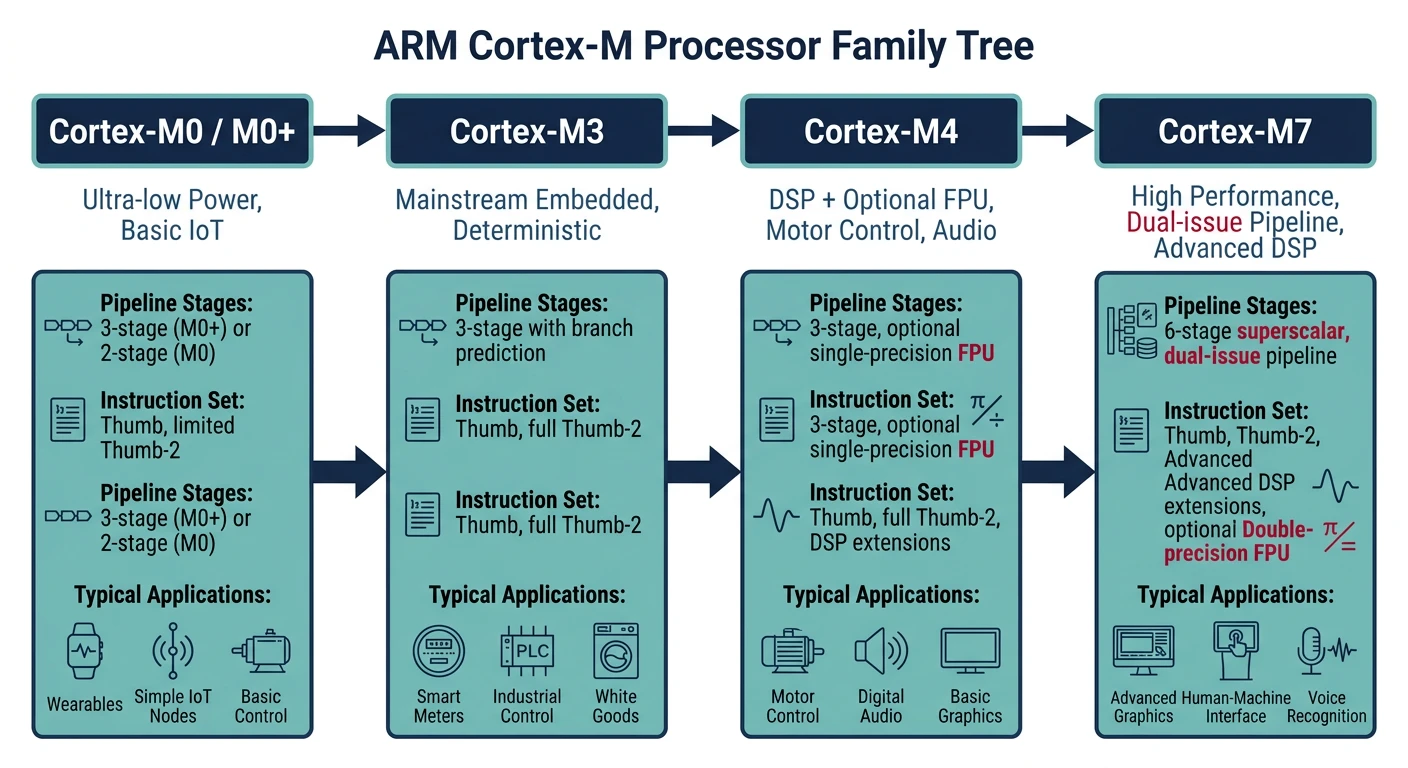
Cortex-M Family Comparison
| Feature | M0/M0+ | M3 | M4 | M7 |
|---|---|---|---|---|
| Pipeline | 2-stage | 3-stage | 3-stage | 6-stage |
| DSP Instructions | No | No | Yes | Yes |
| FPU | No | No | Optional (SP) | SP + DP |
| Cache | No | No | No | I/D Cache |
| Max Frequency | ~48MHz | ~120MHz | ~180MHz | ~400MHz+ |
| Typical Use | Simple sensors | General MCU | Motor, Audio | High-perf DSP |
Cortex-M Programmer's Model
All Cortex-M cores share a common programmer's model:
- 16 general-purpose registers: R0-R12 (general), R13 (SP), R14 (LR), R15 (PC)
- Program Status Registers (xPSR): Flags, exception number, thumb state
- Thumb-2 instruction set: Mix of 16-bit and 32-bit instructions
- Two stack pointers: MSP (Main) and PSP (Process) for OS support
- Two privilege levels: Privileged and Unprivileged (for RTOS)
// Accessing core registers (compiler intrinsics)
#include "cmsis_gcc.h"

uint32_t stack_ptr = __get_MSP();      // Get Main Stack Pointer
uint32_t primask = __get_PRIMASK();    // Get interrupt mask

__disable_irq();  // Disable interrupts globally
// Critical section
__enable_irq();   // Re-enable interrupts

__DSB();  // Data Synchronization Barrier
__ISB();  // Instruction Synchronization Barrier
STM32 Microcontroller Families
STMicroelectronics' STM32 is the most popular ARM Cortex-M implementation, with hundreds of variants organized into families:
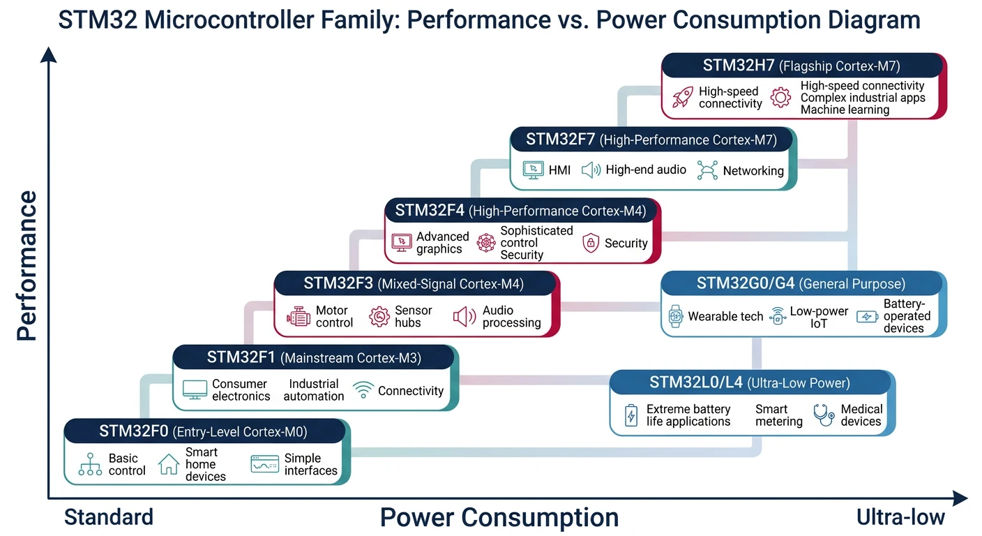
STM32 Family Guide
- STM32F0: Cortex-M0, entry-level, ultra-low-cost ($0.30+)
- STM32F1: Cortex-M3, legacy mainstream, huge ecosystem
- STM32F3: Cortex-M4, analog-rich (ADC, comparators)
- STM32F4: Cortex-M4F, most popular high-performance line
- STM32F7: Cortex-M7, higher speed, caches, LCD controller
- STM32H7: Cortex-M7 @ 480MHz, dual-core options
- STM32L0/L4/L5: Ultra-low-power variants
- STM32G0/G4: Newest mainstream, replaces F0/F3
- STM32U5: Ultra-low-power with TrustZone security
- Cost-sensitive: STM32F0, STM32G0
- General purpose: STM32F4 (best ecosystem)
- Low power: STM32L4, STM32U5
- High performance: STM32H7
- Learning: STM32F4 Discovery, Nucleo boards
Development Environment Setup
STM32CubeIDE Installation
STM32CubeIDE is ST's free, all-in-one IDE combining Eclipse, GCC toolchain, and STM32CubeMX code generator.
# Download from st.com/stm32cubeide (Windows/Mac/Linux)
# Includes:
# - Eclipse-based IDE
# - ARM GCC toolchain
# - ST-Link debugger support
# - STM32CubeMX project configurator

# Alternative: PlatformIO in VS Code
pip install platformio
# Then install STM32 platform in PlatformIO
Project Structure
MySTM32Project/
+-- Core/
│   +-- Inc/              # Header files
│   │   +-- main.h
│   │   +-- stm32f4xx_it.h
│   +-- Src/              # Source files
│       +-- main.c
│       +-- stm32f4xx_it.c   # Interrupt handlers
│       +-- system_stm32f4xx.c
+-- Drivers/
│   +-- CMSIS/            # ARM CMSIS headers
│   +-- STM32F4xx_HAL_Driver/  # HAL library
+-- STM32F446RETX_FLASH.ld   # Linker script
+-- Makefile or .project
HAL Programming Fundamentals
The Hardware Abstraction Layer (HAL) provides portable APIs across STM32 families. While it adds some overhead, it dramatically speeds development.
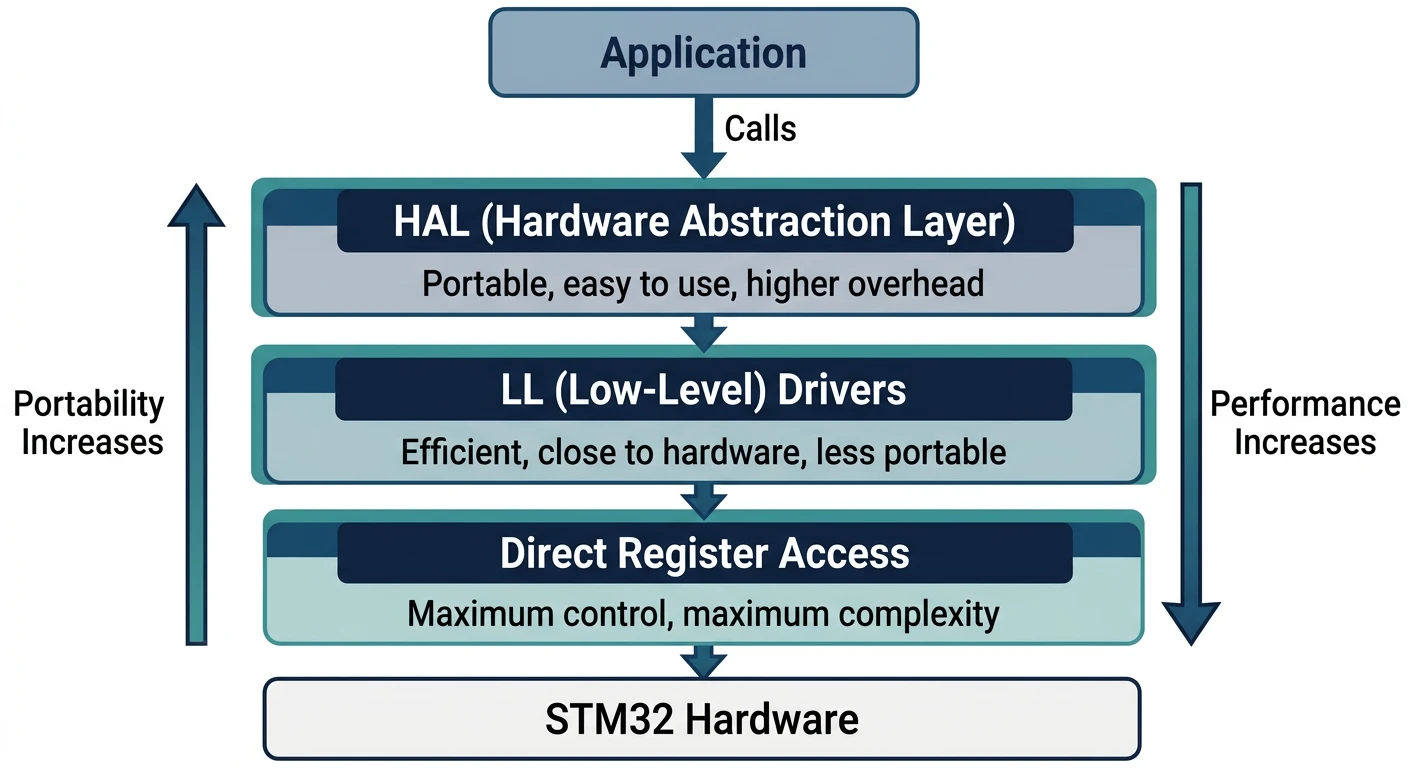
STM32 Software Layers
- HAL (High-Level): Full abstraction, portable, callback-based
- LL (Low-Level): Thin wrappers, close to hardware, faster
- Direct Register: Maximum control, minimum overhead
// HAL initialization pattern
int main(void) {
    // 1. Reset peripherals, initialize Flash and SysTick
    HAL_Init();

    // 2. Configure system clock (generated by CubeMX)
    SystemClock_Config();

    // 3. Initialize peripherals
    MX_GPIO_Init();
    MX_USART2_UART_Init();
    MX_TIM2_Init();

    // 4. Application loop
    while (1) {
        // Your code here
        HAL_Delay(1000);  // Uses SysTick
    }
}

// HAL callback pattern (weak functions to override)
void HAL_GPIO_EXTI_Callback(uint16_t GPIO_Pin) {
    if (GPIO_Pin == USER_BUTTON_Pin) {
        HAL_GPIO_TogglePin(LED_GPIO_Port, LED_Pin);
    }
}
GPIO Configuration & Control
General Purpose Input/Output (GPIO) pins are the fundamental interface between your MCU and the external world.
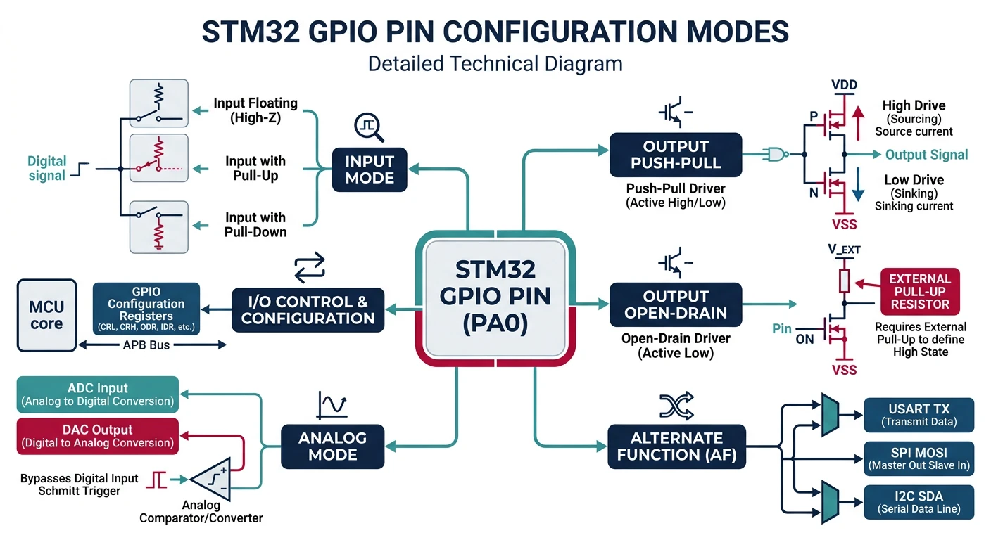
GPIO Modes
- Input: Floating, Pull-up, Pull-down
- Output: Push-Pull, Open-Drain
- Alternate Function: UART, SPI, I2C, PWM, etc.
- Analog: ADC/DAC input
// GPIO configuration with HAL
void MX_GPIO_Init(void) {
    GPIO_InitTypeDef GPIO_InitStruct = {0};

    // Enable GPIO clock
    __HAL_RCC_GPIOA_CLK_ENABLE();

    // Configure PA5 as output (LED on Nucleo boards)
    GPIO_InitStruct.Pin = GPIO_PIN_5;
    GPIO_InitStruct.Mode = GPIO_MODE_OUTPUT_PP;  // Push-Pull
    GPIO_InitStruct.Pull = GPIO_NOPULL;
    GPIO_InitStruct.Speed = GPIO_SPEED_FREQ_LOW;
    HAL_GPIO_Init(GPIOA, &GPIO_InitStruct);

    // Configure PC13 as input with interrupt (User button)
    GPIO_InitStruct.Pin = GPIO_PIN_13;
    GPIO_InitStruct.Mode = GPIO_MODE_IT_FALLING;  // Interrupt on falling edge
    GPIO_InitStruct.Pull = GPIO_PULLUP;
    HAL_GPIO_Init(GPIOC, &GPIO_InitStruct);

    // Enable EXTI interrupt
    HAL_NVIC_SetPriority(EXTI15_10_IRQn, 0, 0);
    HAL_NVIC_EnableIRQ(EXTI15_10_IRQn);
}

// GPIO control
HAL_GPIO_WritePin(GPIOA, GPIO_PIN_5, GPIO_PIN_SET);    // Set high
HAL_GPIO_WritePin(GPIOA, GPIO_PIN_5, GPIO_PIN_RESET);  // Set low
HAL_GPIO_TogglePin(GPIOA, GPIO_PIN_5);                 // Toggle

GPIO_PinState state = HAL_GPIO_ReadPin(GPIOC, GPIO_PIN_13);  // Read
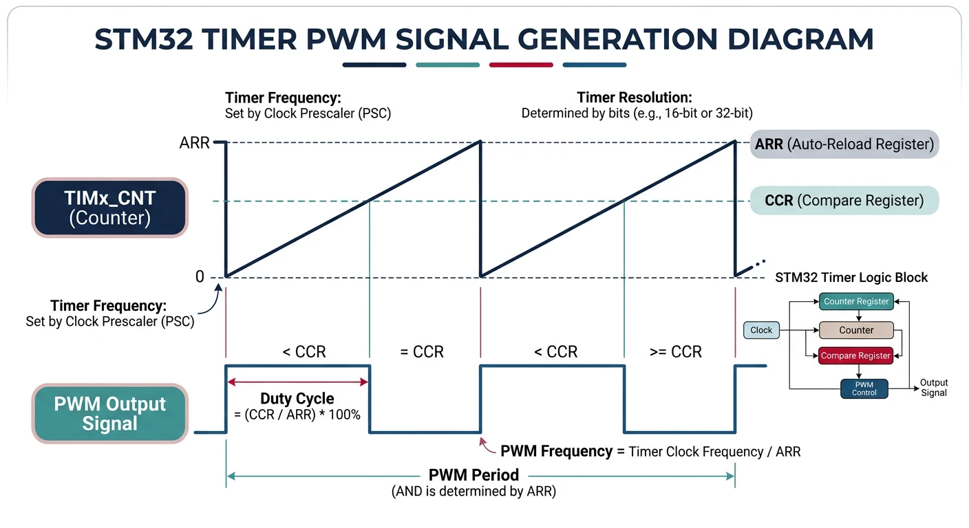
Timers & PWM
STM32 timers are incredibly versatile—used for delays, PWM generation, input capture, and event counting.
Timer Types
- Basic (TIM6, TIM7): Simple counting, DAC triggers
- General Purpose (TIM2-5): 4 channels, capture/compare, PWM
- Advanced (TIM1, TIM8): Motor control, complementary outputs, break input
// Timer-based delay (using TIM2)
void TIM2_Init(void) {
    __HAL_RCC_TIM2_CLK_ENABLE();

    htim2.Instance = TIM2;
    htim2.Init.Prescaler = 84 - 1;      // 84MHz / 84 = 1MHz (1µs ticks)
    htim2.Init.CounterMode = TIM_COUNTERMODE_UP;
    htim2.Init.Period = 0xFFFFFFFF;     // 32-bit timer
    htim2.Init.ClockDivision = TIM_CLOCKDIVISION_DIV1;
    HAL_TIM_Base_Init(&htim2);
    HAL_TIM_Base_Start(&htim2);
}

void delay_us(uint32_t us) {
    uint32_t start = __HAL_TIM_GET_COUNTER(&htim2);
    while ((__HAL_TIM_GET_COUNTER(&htim2) - start) < us);
}

// PWM Generation (LED brightness control)
void PWM_Init(void) {
    TIM_OC_InitTypeDef sConfigOC = {0};

    htim3.Instance = TIM3;
    htim3.Init.Prescaler = 84 - 1;      // 1µs resolution
    htim3.Init.Period = 1000 - 1;       // 1kHz PWM frequency
    HAL_TIM_PWM_Init(&htim3);

    sConfigOC.OCMode = TIM_OCMODE_PWM1;
    sConfigOC.Pulse = 500;              // 50% duty cycle
    sConfigOC.OCPolarity = TIM_OCPOLARITY_HIGH;
    HAL_TIM_PWM_ConfigChannel(&htim3, &sConfigOC, TIM_CHANNEL_1);

    HAL_TIM_PWM_Start(&htim3, TIM_CHANNEL_1);
}

// Change duty cycle at runtime
void set_brightness(uint16_t duty) {  // 0-1000
    __HAL_TIM_SET_COMPARE(&htim3, TIM_CHANNEL_1, duty);
}
UART Communication
UART is the simplest serial protocol—essential for debugging, console output, and communication with sensors and modules.
// UART initialization (115200 baud, 8N1)
UART_HandleTypeDef huart2;

void MX_USART2_UART_Init(void) {
    huart2.Instance = USART2;
    huart2.Init.BaudRate = 115200;
    huart2.Init.WordLength = UART_WORDLENGTH_8B;
    huart2.Init.StopBits = UART_STOPBITS_1;
    huart2.Init.Parity = UART_PARITY_NONE;
    huart2.Init.Mode = UART_MODE_TX_RX;
    huart2.Init.HwFlowCtl = UART_HWCONTROL_NONE;
    HAL_UART_Init(&huart2);
}

// Blocking transmit
char msg[] = "Hello STM32!\r\n";
HAL_UART_Transmit(&huart2, (uint8_t*)msg, strlen(msg), HAL_MAX_DELAY);

// Blocking receive
uint8_t rx_buffer[64];
HAL_UART_Receive(&huart2, rx_buffer, 10, 1000);  // 1s timeout

// Interrupt-driven receive (non-blocking)
void start_uart_rx(void) {
    HAL_UART_Receive_IT(&huart2, &rx_byte, 1);
}

void HAL_UART_RxCpltCallback(UART_HandleTypeDef *huart) {
    if (huart == &huart2) {
        process_byte(rx_byte);
        HAL_UART_Receive_IT(&huart2, &rx_byte, 1);  // Restart
    }
}

// printf redirect (for debugging)
int _write(int file, char *ptr, int len) {
    HAL_UART_Transmit(&huart2, (uint8_t*)ptr, len, HAL_MAX_DELAY);
    return len;
}
ADC & DAC Peripherals
ADC (Analog-to-Digital Converter)
STM32 ADCs convert analog voltages to digital values—essential for reading sensors like temperature, light, and potentiometers.
// ADC configuration (12-bit, single conversion)
ADC_HandleTypeDef hadc1;

void MX_ADC1_Init(void) {
    ADC_ChannelConfTypeDef sConfig = {0};

    hadc1.Instance = ADC1;
    hadc1.Init.ClockPrescaler = ADC_CLOCK_SYNC_PCLK_DIV4;
    hadc1.Init.Resolution = ADC_RESOLUTION_12B;
    hadc1.Init.ScanConvMode = DISABLE;
    hadc1.Init.ContinuousConvMode = DISABLE;
    hadc1.Init.ExternalTrigConvEdge = ADC_EXTERNALTRIGCONVEDGE_NONE;
    hadc1.Init.DataAlign = ADC_DATAALIGN_RIGHT;
    hadc1.Init.NbrOfConversion = 1;
    HAL_ADC_Init(&hadc1);

    // Configure channel (PA0 = ADC1_IN0)
    sConfig.Channel = ADC_CHANNEL_0;
    sConfig.Rank = 1;
    sConfig.SamplingTime = ADC_SAMPLETIME_84CYCLES;
    HAL_ADC_ConfigChannel(&hadc1, &sConfig);
}

// Read ADC value
uint16_t read_adc(void) {
    HAL_ADC_Start(&hadc1);
    HAL_ADC_PollForConversion(&hadc1, HAL_MAX_DELAY);
    return HAL_ADC_GetValue(&hadc1);  // 0-4095 for 12-bit
}

// Convert to voltage (assuming 3.3V reference)
float read_voltage(void) {
    return (read_adc() * 3.3f) / 4095.0f;
}
DAC (Digital-to-Analog Converter)
// DAC configuration
DAC_HandleTypeDef hdac;

void MX_DAC_Init(void) {
    DAC_ChannelConfTypeDef sConfig = {0};

    hdac.Instance = DAC;
    HAL_DAC_Init(&hdac);

    sConfig.DAC_Trigger = DAC_TRIGGER_NONE;
    sConfig.DAC_OutputBuffer = DAC_OUTPUTBUFFER_ENABLE;
    HAL_DAC_ConfigChannel(&hdac, &sConfig, DAC_CHANNEL_1);

    HAL_DAC_Start(&hdac, DAC_CHANNEL_1);
}

// Output voltage (0-3.3V mapped to 0-4095)
void set_dac_voltage(float voltage) {
    uint32_t value = (uint32_t)((voltage / 3.3f) * 4095.0f);
    HAL_DAC_SetValue(&hdac, DAC_CHANNEL_1, DAC_ALIGN_12B_R, value);
}
DMA (Direct Memory Access)
DMA transfers data between memory and peripherals without CPU involvement—crucial for high-throughput applications like audio, ADC streaming, and communication.
- CPU is free to do other work during transfers
- Higher throughput than interrupt-driven I/O
- Essential for audio, video, high-speed comms
- Lower latency for peripheral-to-memory transfers
// DMA-based UART transmit
DMA_HandleTypeDef hdma_usart2_tx;

void DMA_Init(void) {
    __HAL_RCC_DMA1_CLK_ENABLE();

    hdma_usart2_tx.Instance = DMA1_Stream6;
    hdma_usart2_tx.Init.Channel = DMA_CHANNEL_4;
    hdma_usart2_tx.Init.Direction = DMA_MEMORY_TO_PERIPH;
    hdma_usart2_tx.Init.PeriphInc = DMA_PINC_DISABLE;
    hdma_usart2_tx.Init.MemInc = DMA_MINC_ENABLE;
    hdma_usart2_tx.Init.PeriphDataAlignment = DMA_PDATAALIGN_BYTE;
    hdma_usart2_tx.Init.MemDataAlignment = DMA_MDATAALIGN_BYTE;
    hdma_usart2_tx.Init.Mode = DMA_NORMAL;
    hdma_usart2_tx.Init.Priority = DMA_PRIORITY_LOW;
    HAL_DMA_Init(&hdma_usart2_tx);

    __HAL_LINKDMA(&huart2, hdmatx, hdma_usart2_tx);
}

// Non-blocking transmit with DMA
uint8_t large_buffer[1024];
HAL_UART_Transmit_DMA(&huart2, large_buffer, 1024);

// Callback when DMA transfer complete
void HAL_UART_TxCpltCallback(UART_HandleTypeDef *huart) {
    // Transfer complete, start next or signal completion
}

// DMA-based ADC continuous conversion (circular mode)
uint16_t adc_buffer[100];

void start_adc_dma(void) {
    HAL_ADC_Start_DMA(&hadc1, (uint32_t*)adc_buffer, 100);
}

void HAL_ADC_ConvCpltCallback(ADC_HandleTypeDef* hadc) {
    // Buffer full, process or signal
}
Conclusion & What's Next
You've now mastered the core STM32 development skills—understanding ARM Cortex-M architecture, configuring GPIO, timers, UART, ADC/DAC, and DMA. These fundamentals apply across all STM32 families and most ARM-based microcontrollers.
- Cortex-M0/M3/M4/M7 differ in performance and features (DSP, FPU)
- STM32CubeIDE + HAL libraries accelerate development
- GPIO modes: Input, Output, Alternate Function, Analog
- Timers are versatile: delays, PWM, capture, counting
- DMA offloads data transfers from the CPU
In Part 3, we'll dive into Real-Time Operating Systems (RTOS) with FreeRTOS and Zephyr—essential for complex multi-tasking embedded applications.