Introduction
ARM Assembly Mastery
Architecture History & Core Concepts
ARMv1→v9, RISC philosophy, profilesARM32 Instruction Set Fundamentals
ARM vs Thumb, registers, CPSR, barrel shifterAArch64 Registers, Addressing & Data Movement
X/W regs, addressing modes, load/store pairsArithmetic, Logic & Bit Manipulation
ADD/SUB, bitfield extract/insert, CLZBranching, Loops & Conditional Execution
Branch types, link register, jump tablesStack, Subroutines & AAPCS
Calling conventions, prologue/epilogueMemory Model, Caches & Barriers
Weak ordering, DMB/DSB/ISB, TLBNEON & Advanced SIMD
Vector ops, intrinsics, media processingSVE & SVE2 Scalable Vector Extensions
Predicate regs, gather/scatter, HPC/MLFloating-Point & VFP Instructions
IEEE-754, scalar FP, rounding modesException Levels, Interrupts & Vector Tables
EL0–EL3, GIC, fault debuggingMMU, Page Tables & Virtual Memory
Stage-1 translation, permissions, huge pagesTrustZone & ARM Security Extensions
Secure monitor, world switching, TF-ACortex-M Assembly & Bare-Metal Embedded
NVIC, SysTick, linker scripts, low-powerCortex-A System Programming & Boot
EL3→EL1 transitions, MMU setup, PSCIApple Silicon & macOS ABI
ARM64e PAC, Mach-O, dyld, perf countersInline Assembly, GCC/Clang & C Interop
Constraints, clobbers, compiler interactionPerformance Profiling & Micro-Optimization
Pipeline hazards, PMU, benchmarkingReverse Engineering & ARM Binary Analysis
ELF, disassembly, CFR, iOS/Android quirksBuilding a Bare-Metal OS Kernel
Bootloader, UART, scheduler, context switchARM Microarchitecture Deep Dive
OOO pipelines, reorder buffers, branch predictVirtualization Extensions
EL2 hypervisor, stage-2 translation, KVMDebugging & Tooling Ecosystem
GDB, OpenOCD/JTAG, ETM/ITM, QEMULinkers, Loaders & Binary Format Internals
ELF deep dive, relocations, PIC, crt0Cross-Compilation & Build Systems
GCC/Clang toolchains, CMake, firmware genARM in Real Systems
Android, FreeRTOS/Zephyr, U-Boot, TF-ASecurity Research & Exploitation
ASLR, PAC attacks, ROP/JOP, kernel exploitEmerging ARMv9 & Future Directions
MTE, SME, confidential compute, AI accelAArch64 Overview
AArch64 is the 64-bit execution state introduced with ARMv8-A in 2011. It represents a clean-sheet redesign — not merely an extension of the 32-bit ARM instruction set but a fundamentally different architecture that happens to share the same silicon. Where AArch32 evolved through decades of accumulated features (Thumb, Thumb-2, NEON, Jazelle), AArch64 starts fresh with an orthogonal, RISC-pure design that modern compilers love.
Think of it like this: AArch32 is a charming old house with rooms added over the years — functional but full of quirky hallways. AArch64 is the architect's clean modern build — open plan, every room the same height, every door the same width. Both are livable, but only one was designed with a unified vision.
aarch64-linux-gnu. We'll use AArch64 consistently throughout this series.
Key Differences from ARM32
If you've worked through Part 2, you know ARM32's personality: 16 registers, banked register sets per exception mode, a barrel shifter wired into every data-processing instruction, and conditional execution on almost every opcode. AArch64 throws most of that away and replaces it with cleaner alternatives:
| Feature | AArch32 (ARM32) | AArch64 |
|---|---|---|
| GP Registers | 16 (R0–R15, with R13=SP, R14=LR, R15=PC) | 31 (X0–X30) + SP + XZR |
| Register Width | 32-bit only | 64-bit (X) with 32-bit (W) aliases |
| Banked Registers | Yes — separate R13/R14 per mode | No — single register file; exception state saved to memory |
| Condition Codes | Every instruction can be conditional (EQ, NE, etc.) | Only branches and a few select instructions (CSEL, CSINC, CCMP) |
| Barrel Shifter | Inline on every data-processing operand | Limited shift amounts on some instructions; separate shift insns |
| PC Access | R15 is both PC and a GP register | PC is not a GP register — no MOV x0, pc |
| Addressing | Many complex modes, incl. register-list LDM/STM | Clean base+offset, register offset, pre/post-index only |
| Zero Register | None — must MOV r0, #0 | XZR/WZR — hardwired zero |
| SIMD/FP Regs | 32 × 64-bit (D0–D31) or 16 × 128-bit (Q0–Q15) | 32 × 128-bit (V0–V31) with B/H/S/D/Q views |
| System Registers | CPSR + coprocessor MCR/MRC | PSTATE fields + named system registers via MRS/MSR |
The result is an architecture that generates shorter, faster code — compilers can keep more values in registers, avoid stack spills, and produce denser instruction streams. Apple's transition to AArch64 with the A7 chip in 2013 proved that AArch64 code could outperform AArch32 by 15-30% even at the same clock speed, largely due to the wider register file and cleaner ISA.
General-Purpose Registers
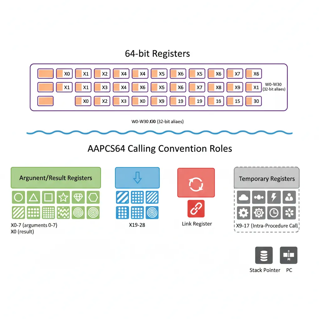
AArch64 provides 31 general-purpose registers (X0–X30), each 64 bits wide, plus a dedicated stack pointer (SP) and a zero register (XZR/WZR). This is nearly double ARM32's 16-register file, and the impact on compiler performance is dramatic: fewer register spills, less stack traffic, and simpler calling conventions.
Imagine your workspace desk: ARM32 gives you 16 small trays for papers — you're constantly shuffling documents to the filing cabinet (stack) and back. AArch64 gives you 31 full-size trays, each twice as deep. You rarely need the cabinet at all.
X Registers (64-bit) & W Aliases (32-bit)
The 31 registers have two names each: X0–X30 for 64-bit access and W0–W30 for 32-bit access. These are not separate registers — W0 is simply the lower 32 bits of X0. The critical rule: writing to a W register zero-extends the result into the full 64-bit X register, clearing the upper 32 bits. This eliminates an entire class of bugs where stale upper bits could corrupt 64-bit pointer arithmetic.
| Register | 64-bit Name | 32-bit Name | AAPCS64 Role |
|---|---|---|---|
| 0–7 | X0–X7 | W0–W7 | Arguments / return values |
| 8 | X8 | W8 | Indirect result location (struct return) |
| 9–15 | X9–X15 | W9–W15 | Temporary (caller-saved) |
| 16–17 | X16–X17 (IP0/IP1) | W16–W17 | Intra-procedure scratch (linker veneers) |
| 18 | X18 (PR) | W18 | Platform register (reserved on some OSes) |
| 19–28 | X19–X28 | W19–W28 | Callee-saved (must preserve across calls) |
| 29 | X29 (FP) | W29 | Frame pointer |
| 30 | X30 (LR) | W30 | Link register (return address) |
// AArch64: W register zero-extends to X
    MOV  w0, #42          // x0 = 0x000000000000002A
    MOV  x1, #0xFFFF
    MOV  w1, #1           // x1 = 0x0000000000000001  (upper 32 bits cleared)

    // Common pattern: use W registers for 32-bit data types (int, float)
    LDR  w3, [x0]         // Load 32-bit int; x3 upper 32 bits = 0
    ADD  w3, w3, #1       // 32-bit arithmetic; zero-extends result
    STR  w3, [x0]         // Store back 32-bit int

    // Use X registers for pointers and 64-bit data (long, size_t)
    LDR  x4, [x1]         // Load 64-bit pointer
ADD x4, x4, #8 // 64-bit pointer arithmeticADD x0, w1, w2 is illegal — you'll get an assembler error. If you need to promote a 32-bit value to 64-bit, use UXTW (unsigned extend word) or SXTW (signed extend word), or simply read from the X name after a W write (since it's already zero-extended).
XZR/WZR — Zero Register
One of AArch64's most elegant features is the zero register — XZR (64-bit) and WZR (32-bit). Reading from XZR always returns 0; writing to XZR discards the result silently. This simple idea eliminates an entire category of instructions and enables powerful idioms:
// Zero register idioms
    MOV  x0, xzr           // Clear register (encoded as ORR x0, xzr, xzr)
    CMP  x1, xzr           // Compare against zero
    ADD  x2, x3, xzr       // Copy register (x2 = x3 + 0)
    STR  xzr, [x0]         // Store zero to memory (no need to clear a reg first!)
    CSEL x4, x5, xzr, EQ   // x4 = (flags == EQ) ? x5 : 0

    // XZR as a "black hole" — discard computation results
    ADDS xzr, x1, x2       // Set flags from x1+x2, discard sum (like CMP)
SUBS xzr, x3, #10 // Set flags from x3-10, discard resultr31; you write xzr or sp depending on context.
SP — Stack Pointer
The stack pointer is a dedicated 64-bit register, separate from the GP file. Unlike ARM32 where SP was just R13 (a general-purpose register used by convention), AArch64's SP has hardware-enforced rules:
- 16-byte alignment: At EL0 (user mode), any memory access through SP must be 16-byte aligned, or the processor raises an alignment fault. This ensures compatibility with SIMD instructions and simplifies cache design.
- Limited instruction support: SP can be used in address calculations (
LDR x0, [sp, #16]) and arithmetic (ADD x0, sp, #32), but not in all instructions — you can't writeAND x0, sp, #mask. - Per-exception-level SP: Each exception level (EL0–EL3) has its own SP —
SP_EL0,SP_EL1,SP_EL2,SP_EL3. At EL1+, you can choose between using SP_EL0 or the current level's SP via theSPSelPSTATE bit.
// SP usage patterns
    MOV  x0, sp             // Read current stack pointer into x0
    ADD  sp, sp, #64        // Deallocate 64 bytes of stack space
    SUB  sp, sp, #128       // Allocate 128 bytes of stack space

    // SP must stay 16-byte aligned
    SUB  sp, sp, #16        // OK: 16-byte aligned
    SUB  sp, sp, #32        // OK: 16-byte aligned
    // SUB  sp, sp, #12     // DANGER: misaligns SP → alignment fault on access
X29 (FP) & X30 (LR)
Two registers have special architectural or conventional significance:
X29 — Frame Pointer (FP): By AAPCS64 convention, X29 points to the base of the current stack frame. This enables debuggers and profilers to walk the call stack by following the chain of saved frame pointers. While technically optional (compilers can use -fomit-frame-pointer to reclaim X29 as a general register), most production builds preserve it for reliable crash diagnostics.
X30 — Link Register (LR): When you execute BL label (Branch with Link), the processor stores the return address in X30. The RET instruction then branches to X30 by default. Critical difference from ARM32: BL does not push LR onto the stack — if your function calls another function, you must save X30 yourself (typically via STP x29, x30, [sp, #-16]!).
The Unsaved Link Register Bug
A common beginner mistake in AArch64: calling a subroutine without saving LR. Consider a function foo that calls bar. When foo executes BL bar, X30 is overwritten with the return address back to foo. But foo's own return address (back to its caller) was also in X30 — and it's now lost. When foo tries to RET, it jumps to the wrong address, causing an infinite loop or crash. The fix: always save LR in the prologue of any non-leaf function.
System Registers
AArch64 replaces ARM32's coprocessor-based system configuration (MCR/MRC to CP15) with a clean, named system register architecture. There are hundreds of system registers controlling everything from cache policy to virtualization, all accessed through just two instructions: MRS (read) and MSR (write). Think of system registers as the processor's control panel — each register is a labelled switch or dial, and MRS/MSR are the only hands allowed to turn them.
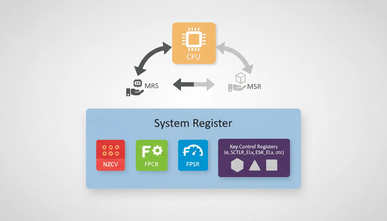
NZCV — Condition Flags
The four classic condition flags live in their own system register called NZCV:
| Flag | Bit | Name | Set When |
|---|---|---|---|
| N | 31 | Negative | Result has its sign bit set (bit 63 for X, bit 31 for W) |
| Z | 30 | Zero | Result is exactly zero |
| C | 29 | Carry | Unsigned overflow (carry out) from addition, or NOT borrow from subtraction |
| V | 28 | Overflow | Signed overflow (sign change that shouldn't have happened) |
Unlike ARM32 where CPSR held flags, interrupt masks, and execution mode all in one register, AArch64 splits these into separate PSTATE fields. The NZCV flags are only modified by instructions that explicitly set them (ADDS, SUBS, CMP, TST, CCMP, etc.) — a plain ADD does not touch flags.
// Flag-setting in AArch64
    ADD   x0, x1, x2       // x0 = x1 + x2; flags UNCHANGED
    ADDS  x0, x1, x2       // x0 = x1 + x2; NZCV updated
    CMP   x3, #100          // Alias for SUBS xzr, x3, #100; flags set, result discarded
    TST   x4, #0xFF         // Alias for ANDS xzr, x4, #0xFF; test low byte

    // Read NZCV into a GP register
    MRS   x5, NZCV          // x5[31:28] = N,Z,C,V bits
FPSR & FPCR
Floating-point operations have their own pair of control/status registers:
FPCR (Floating-Point Control Register) controls behaviour:
- RMode (bits 23:22): Rounding mode — Round to Nearest (00), Round towards Plus Infinity (01), Round towards Minus Infinity (10), Round towards Zero (11)
- FZ (bit 24): Flush-to-zero mode for denormalized numbers (faster but less precise)
- AH, DH, FZ16: Half-precision and alternate handling controls
- IDE, IXE, UFE, OFE, DZE, IOE: Individual exception trap enables
FPSR (Floating-Point Status Register) records what happened:
- QC (bit 27): Cumulative NEON saturation flag
- IDC, IXC, UFC, OFC, DZC, IOC: Cumulative exception flags (Invalid Operation, Inexact, Underflow, Overflow, Divide-by-Zero)
// Configure flush-to-zero for performance
    MRS   x0, FPCR
    ORR   x0, x0, #(1 << 24)    // Set FZ bit
    MSR   FPCR, x0

    // Check for floating-point exceptions
    MRS   x1, FPSR
    TST   x1, #0x01              // Test IOC (Invalid Operation) flag
    B.NE  handle_fp_error
MRS/MSR Access
MRS (Move to Register from System register) and MSR (Move to System Register from register) are the universal gateway to all system registers. This is a dramatic simplification from ARM32, where different coprocessor numbers and opcodes were needed for different system functions.
// Read and write system registers
    MRS  x0, NZCV           // Read condition flags into x0
    MRS  x1, FPCR           // Read FP control register
    MSR  FPCR, x1           // Write FP control register
    MRS  x2, CurrentEL      // Read current exception level

    // System registers at higher ELs (kernel/hypervisor)
    MRS  x3, SCTLR_EL1      // System Control Register (EL1)
    MRS  x4, MAIR_EL1       // Memory Attribute Indirection Register
    MRS  x5, TCR_EL1        // Translation Control Register
MRS x6, TTBR0_EL1 // Translation Table Base Register 0SCTLR_EL1 from EL0 (user space) triggers an illegal instruction exception. The _ELn suffix tells you exactly which privilege level is required. Registers without a suffix (like NZCV) are accessible from any level.
PSTATE Fields
PSTATE is AArch64's replacement for CPSR — but it's not a single register you can read in one shot. Instead, it's a collection of independently-accessible processor state bits. Key fields:
| Field | Bits | Purpose | Access |
|---|---|---|---|
| N, Z, C, V | 31–28 | Condition flags | MRS/MSR NZCV |
| SS | 21 | Software Step (debug single-stepping) | Debug exception |
| IL | 20 | Illegal Execution State (e.g., impossible EL/mode combo) | Exception entry |
| D | 9 | Debug exception mask | MSR DAIFSet/DAIFClr |
| A | 8 | SError (asynchronous abort) mask | MSR DAIFSet/DAIFClr |
| I | 7 | IRQ mask | MSR DAIFSet/DAIFClr |
| F | 6 | FIQ mask | MSR DAIFSet/DAIFClr |
| nRW | — | Execution state: 0 = AArch64, 1 = AArch32 | Exception level change |
| EL | 3:2 | Current Exception Level (0–3) | MRS CurrentEL |
| SP | 0 | Stack pointer select: 0 = SP_EL0, 1 = SP_ELx | MSR SPSel |
// Interrupt mask manipulation (DAIF)
    MSR  DAIFSet, #0xF       // Mask all: D, A, I, F (critical section)
    // ... critical code ...
    MSR  DAIFClr, #0x3       // Unmask I and F only (bits 1:0 = IF)

    // Read current exception level
    MRS  x0, CurrentEL       // x0[3:2] = current EL
    LSR  x0, x0, #2          // x0 = 0 (EL0), 1 (EL1), 2 (EL2), 3 (EL3)

    // Check execution state
    MRS  x1, CurrentEL       // Check: are we at EL1?
    CMP  x1, #(1 << 2)       // EL1 encoded as 0b0100
    B.NE not_kernel
Addressing Modes
AArch64 is a strict load/store architecture: all computation happens in registers, and the only way to move data between registers and memory is through load/store instructions. The addressing modes determine how those memory addresses are calculated. AArch64 offers five clean addressing modes, a significant simplification from ARM32's dozen-plus variants.
Think of addressing modes as different ways to tell a taxi driver where to go: "Go to 123 Main Street" (absolute), "Go 3 blocks north from here" (offset), "Drop me off, then drive 2 blocks east" (post-index), "Drive 2 blocks east, then drop me off" (pre-index).
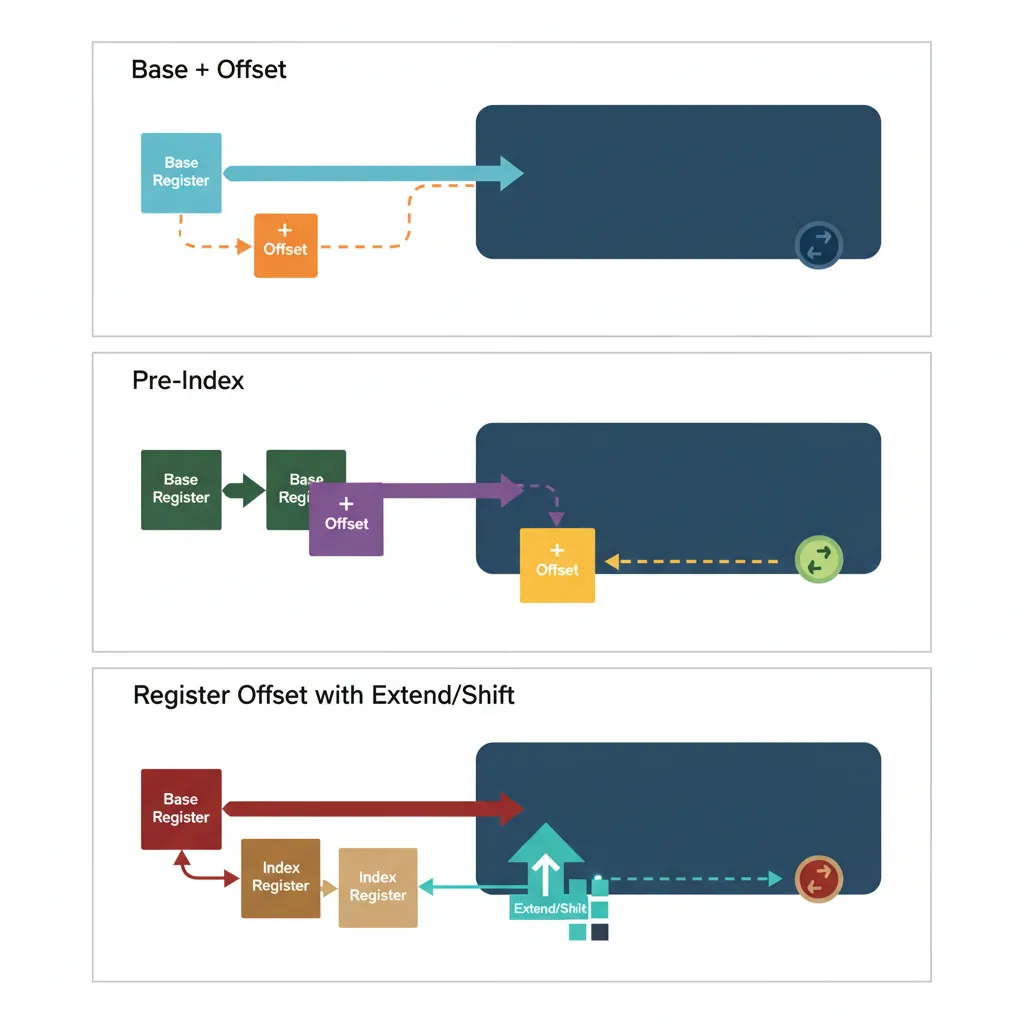
Base Register + Immediate Offset
The most common addressing mode uses a base register plus a constant offset: [Xbase, #imm]. AArch64 supports two flavours:
| Form | Offset Range | Scaling | Use Case |
|---|---|---|---|
LDR Xt, [Xn, #imm] | 0 to 32760 (for 8-byte) | Scaled by access size (12-bit unsigned × size) | Struct fields, array elements |
LDUR Xt, [Xn, #simm] | −256 to +255 | Unscaled (9-bit signed, byte granularity) | Unaligned access, negative offsets |
// Base + immediate offset addressing
    LDR  x0, [x1]            // x0 = Mem[x1 + 0]  (zero offset)
    LDR  x0, [x1, #8]        // x0 = Mem[x1 + 8]  (next 64-bit slot)
    LDR  x0, [x1, #32760]    // Max scaled offset for 8-byte load
    LDR  w0, [x1, #16380]    // Max scaled offset for 4-byte load (4095×4)

    // Unscaled form for odd offsets and negative displacement
    LDUR x0, [x1, #-8]       // x0 = Mem[x1 - 8]  (previous slot)
LDUR w0, [x1, #3] // Unaligned 4-byte load at odd offsetRegister Offset with Extend/Shift
For array indexing, AArch64 allows a second register as the offset, with optional shift or extension. This eliminates a separate multiply/shift instruction for common array access patterns:
// Register offset addressing examples
    LDR  x0, [x1, x2]            // x0 = Mem[x1 + x2]
    LDR  x0, [x1, x2, LSL #3]    // x0 = Mem[x1 + x2*8]  (64-bit array)
    LDR  w0, [x1, w2, UXTW #2]   // w0 = Mem[x1 + zero_extend(w2)*4]
    LDR  x0, [x1, w2, SXTW]      // x0 = Mem[x1 + sign_extend(w2)]
LDR x0, [x1, x2, SXTX #3] // x0 = Mem[x1 + sign_extend(x2)*8]C Array Access → AArch64 Idiom
The C expression array[i] where array is a long* translates to a single instruction: LDR x0, [x1, x2, LSL #3] where x1 = array and x2 = i. The LSL #3 multiplies the index by 8 (sizeof(long)). For int*, use LDR w0, [x1, x2, LSL #2]. No separate shift or multiply instruction needed — the address calculation happens inside the load unit.
Pre-Index & Post-Index
Writeback addressing modes modify the base register as a side effect, combining a load/store with a pointer update in one instruction. These are essential for sequential buffer traversal and stack operations:
// Pre-indexed: update base BEFORE the access
    LDR  x0, [x1, #16]!     // x1 = x1 + 16; then x0 = Mem[x1]
    STR  x0, [sp, #-16]!    // sp = sp - 16; then Mem[sp] = x0 (push)

    // Post-indexed: access THEN update base
    LDR  x0, [x1], #8       // x0 = Mem[x1]; then x1 = x1 + 8
    STR  x0, [x2], #4       // Mem[x2] = x0; then x2 = x2 + 4

    // Buffer copy using post-index (memcpy-like)
copy_loop:
    LDR  x3, [x0], #8       // Load from src; src += 8
    STR  x3, [x1], #8       // Store to dst; dst += 8
    SUBS x2, x2, #1         // Decrement count
B.NE copy_loop // Repeat until count == 0[x1, #16]!. For post-indexed, the offset comes after the bracket: [x1], #8. A common mistake is confusing these, which leads to off-by-one pointer bugs that are painful to debug.
PC-Relative (ADR/ADRP)
Since the Program Counter is not a general-purpose register in AArch64, you can't simply write ADD x0, pc, #offset. Instead, two dedicated instructions provide PC-relative addressing for position-independent code (PIC):
| Instruction | Range | Alignment | Purpose |
|---|---|---|---|
ADR Xd, label | ±1 MB | Byte | Nearby labels within same page |
ADRP Xd, label | ±4 GB | 4 KB page | Page address of far labels |
// PC-relative addressing (PIC pattern)
    ADRP  x0, mydata          // x0 = page containing mydata
    ADD   x0, x0, :lo12:mydata // x0 = exact address of mydata
    LDR   x1, [x0]            // load from mydata

    // Short-range PC-relative (within ±1MB)
    ADR   x2, nearby_label     // x2 = PC + offset (21-bit signed)

    // GOT-based PIC for shared libraries
    ADRP  x0, :got:extern_func
    LDR   x0, [x0, :got_lo12:extern_func]
BLR x0 // Call through GOT entryLiteral Pools
When you need to load a 64-bit constant that can't be encoded with MOVZ/MOVK sequences, the assembler provides a pseudo-instruction:
// Literal pool pseudo-instruction
    LDR  x0, =0xDEADBEEFCAFEBABE  // Assembler places constant in literal pool
                                     // and generates: LDR x0, [PC, #offset]

    // What the assembler actually emits:
    LDR  x0, .Lpool_entry_0        // PC-relative load from literal pool
    // ... more code ...

.Lpool_entry_0:
    .quad 0xDEADBEEFCAFEBABE       // 8 bytes in the literal pool

    // Alternative: explicit MOVZ+MOVK sequence (no literal pool)
    MOVZ x0, #0xBABE               // Load bits [15:0]
    MOVK x0, #0xCAFE, LSL #16      // Insert bits [31:16]
    MOVK x0, #0xBEEF, LSL #32      // Insert bits [47:32]
MOVK x0, #0xDEAD, LSL #48 // Insert bits [63:48]LDR x0, =constant is fine. The assembler's .ltorg directive lets you control where literal pool data is placed.
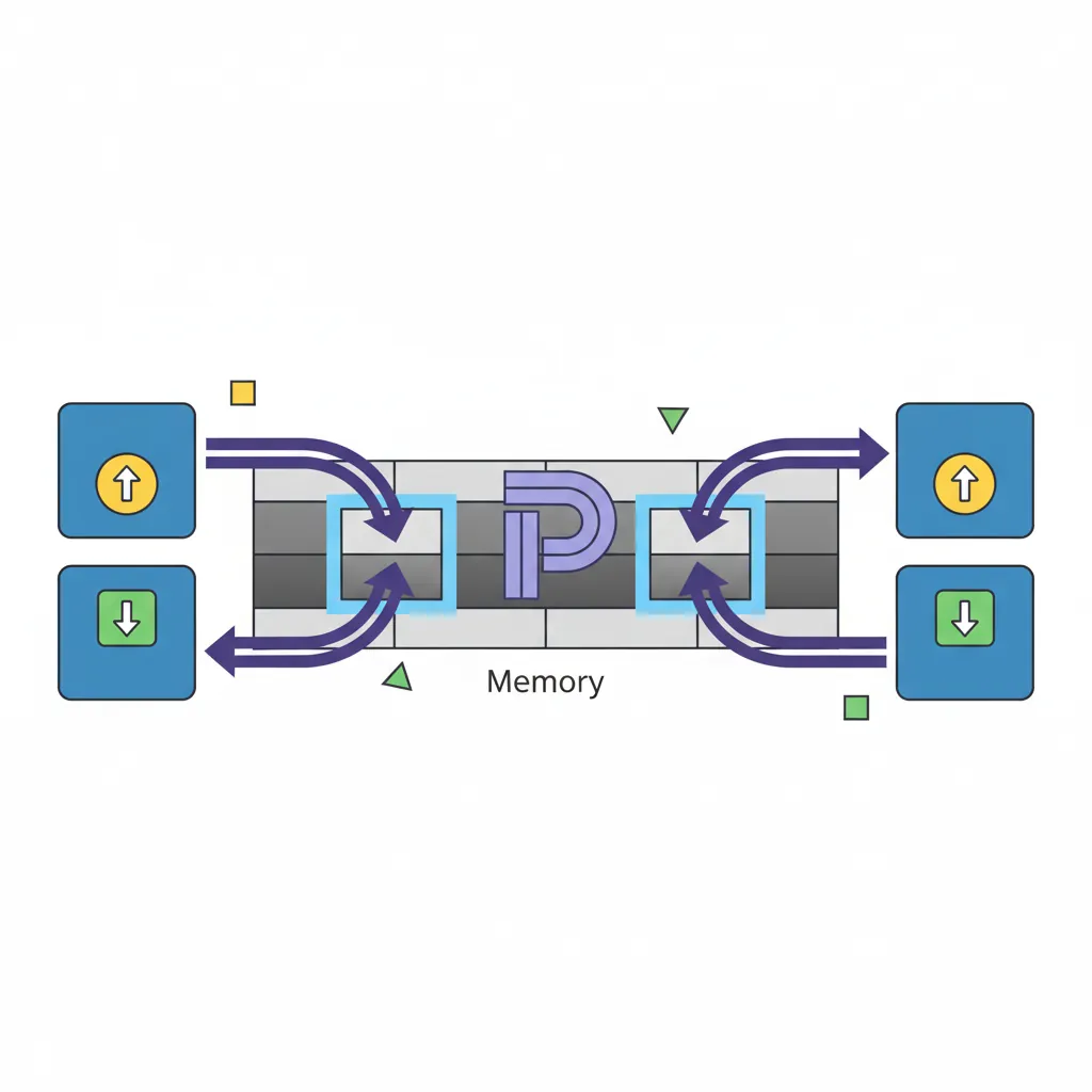
Load/Store Instructions
AArch64 is a strict load/store architecture — every computation happens in registers, and the only way to touch memory is through dedicated load/store instructions. There's no ADD x0, [x1] equivalent like x86's ADD RAX, [RBX]. This constraint keeps the pipeline clean and predictable, at the cost of slightly more instructions for memory-heavy operations.
LDR/STR Width Variants
The load/store family covers every data width from a single byte to a 64-bit doubleword. The register name (W vs X) determines the access size for the base LDR/STR mnemonics:
| Instruction | Width | Destination | Zero-Extends? | C Equivalent |
|---|---|---|---|---|
LDRB Wt, [Xn] | 8-bit (byte) | W register | Yes → 32-bit | uint8_t |
LDRH Wt, [Xn] | 16-bit (halfword) | W register | Yes → 32-bit | uint16_t |
LDR Wt, [Xn] | 32-bit (word) | W register | Yes → 64-bit (via W) | uint32_t |
LDR Xt, [Xn] | 64-bit (doubleword) | X register | N/A (full width) | uint64_t, pointers |
STRB Wt, [Xn] | 8-bit (byte) | — | N/A (store) | uint8_t |
STRH Wt, [Xn] | 16-bit (halfword) | — | N/A (store) | uint16_t |
STR Wt, [Xn] | 32-bit (word) | — | N/A (store) | uint32_t |
STR Xt, [Xn] | 64-bit (doubleword) | — | N/A (store) | uint64_t, pointers |
// Load/Store width variants
    LDRB w0, [x1]         // Load unsigned byte; zero-extends to 32-bit
    LDRH w0, [x1]         // Load unsigned halfword (16-bit)
    LDR  w0, [x1]         // Load 32-bit word
    LDR  x0, [x1]         // Load 64-bit doubleword

    STRB w0, [x1]         // Store low byte of w0
    STRH w0, [x1]         // Store low halfword of w0
    STR  w0, [x1]         // Store 32-bit word
    STR  x0, [x1]         // Store 64-bit doubleword
    STR  xzr, [x1]        // Store zero (no need to clear a register first!)
Sign-Extension Loads (LDRSB, LDRSH, LDRSW)
When loading signed values narrower than the destination register, you need sign extension — the processor copies the sign bit into all the upper bits. Without this, a signed -1 stored as a byte (0xFF) would be loaded as 255 instead of -1:
// Sign-extension loads
    LDRSB w0, [x1]        // Load signed byte; sign-extends to 32-bit
                           // 0xFF → 0xFFFFFFFF (-1 as int32)
    LDRSB x0, [x1]        // Load signed byte; sign-extends to 64-bit
                           // 0xFF → 0xFFFFFFFFFFFFFFFF (-1 as int64)
    LDRSH w0, [x1]        // Load signed halfword; sign-extends to 32-bit
    LDRSH x0, [x1]        // Load signed halfword; sign-extends to 64-bit
    LDRSW x0, [x1]        // Load signed word; sign-extends 32 → 64-bit
                           // Note: LDRSW always uses X destination

    // Unsigned vs signed load comparison
    // Memory contains: 0x80 (128 unsigned, -128 signed)
    LDRB  w0, [x1]        // w0 = 0x00000080 (128)
LDRSB w0, [x1] // w0 = 0xFFFFFF80 (-128)LDRB (unsigned) and LDRSB (signed) is driven directly by the C type: unsigned char compiles to LDRB, while signed char (or plain char on ARM, which is unsigned by default) compiles to LDRSB. Getting the wrong sign extension is a classic source of subtle arithmetic bugs.
Exclusive Load/Store (LDXR/STXR)
Multicore systems need atomic read-modify-write operations to safely share data. AArch64 uses an exclusive monitor pattern: LDXR loads a value and marks the address in a hardware monitor; STXR attempts the store but only succeeds if no other core has touched that cache line since the LDXR. If the store fails, you retry.
// Atomic increment using exclusive load/store
atomic_inc:
    LDXR  w1, [x0]          // Load exclusive; mark x0 in monitor
    ADD   w1, w1, #1        // Increment
    STXR  w2, w1, [x0]      // Store exclusive; w2 = 0 if succeeded
    CBNZ  w2, atomic_inc    // Retry if store failed
    RET

// Compare-and-swap (CAS) pattern
cas_loop:
    LDXR  x1, [x0]          // Load current value
    CMP   x1, x2            // Compare with expected (x2)
    B.NE  cas_fail           // If not equal, CAS fails
    STXR  w3, x4, [x0]      // Try to store new value (x4)
    CBNZ  w3, cas_loop       // Retry if exclusive store failed
cas_fail:
RETLarge System Extensions (LSE) Atomic Instructions
The LDXR/STXR loop pattern works but has overhead on highly-contended cachelines. ARMv8.1-A added LSE (Large System Extensions) with single-instruction atomics: LDADD (atomic add), CAS/CASP (compare-and-swap), SWP (atomic swap), and LDCLR/LDSET (atomic bit clear/set). These are hardware-optimized and can be 2–5× faster than LDXR/STXR loops on multi-socket servers. GCC enables them with -march=armv8.1-a or -moutline-atomics (runtime dispatch).
Acquire/Release Semantics (LDAR/STLR)
In a multicore system, memory operations can be reordered by the processor for performance. This is invisible to single-threaded code but catastrophic for shared-memory synchronization. AArch64 provides acquire/release semantics to enforce ordering without expensive full memory barriers:
| Instruction | Semantics | Ordering Guarantee | C++ Equivalent |
|---|---|---|---|
LDAR Xt, [Xn] | Load-Acquire | No later loads/stores can move before this | load(memory_order_acquire) |
STLR Xt, [Xn] | Store-Release | No earlier loads/stores can move after this | store(memory_order_release) |
LDAXR Xt, [Xn] | Load-Acquire Exclusive | Acquire + exclusive monitor | compare_exchange (acquire) |
STLXR Wt, Xs, [Xn] | Store-Release Exclusive | Release + exclusive store | compare_exchange (release) |
// Mutex lock pattern using acquire/release
mutex_lock:
    MOV   w1, #1
retry:
    LDAXR w0, [x2]          // Load-Acquire Exclusive: read lock
    CBNZ  w0, retry         // If locked, spin
    STXR  w0, w1, [x2]      // Try to set lock = 1
    CBNZ  w0, retry         // Retry if exclusive failed
    RET                      // Lock acquired; acquire fence ensures
                             // subsequent accesses are ordered

mutex_unlock:
    STLR  wzr, [x2]         // Store-Release: lock = 0
    RET                      // Release fence ensures all prior
                             // accesses are visible before unlock
Load/Store Pair Instructions
One of AArch64's most impactful performance features is the ability to load or store two registers in a single instruction. LDP (Load Pair) and STP (Store Pair) transfer two adjacent register-width values simultaneously, effectively doubling memory throughput for sequential access patterns. This is particularly powerful for function prologues/epilogues, structure copies, and context switches.
LDP/STP Basics
LDP Xt1, Xt2, [Xbase, #imm] loads two consecutive values from memory into two registers. STP does the reverse. The immediate offset is a 7-bit signed value scaled by the access size:
| Form | Access Size | Offset Range | Total Bytes |
|---|---|---|---|
LDP Wt1, Wt2, [Xn, #imm] | 2 × 32-bit | −256 to +252 (step 4) | 8 bytes |
LDP Xt1, Xt2, [Xn, #imm] | 2 × 64-bit | −512 to +504 (step 8) | 16 bytes |
LDP Qt1, Qt2, [Xn, #imm] | 2 × 128-bit | −1024 to +1008 (step 16) | 32 bytes |
LDPSW Xt1, Xt2, [Xn, #imm] | 2 × 32-bit (sign-extended) | −256 to +252 (step 4) | 8 bytes |
// LDP/STP basics
    LDP  x0, x1, [x2]         // x0 = Mem[x2]; x1 = Mem[x2+8]
    STP  x3, x4, [x2, #16]    // Mem[x2+16] = x3; Mem[x2+24] = x4
    LDP  w5, w6, [x2]         // w5 = Mem32[x2]; w6 = Mem32[x2+4]
    LDPSW x7, x8, [x2]        // Sign-extend two 32-bit loads to 64-bit

    // Zero-initialize 64 bytes of memory
    STP  xzr, xzr, [x0]       // Clear bytes  0-15
    STP  xzr, xzr, [x0, #16]  // Clear bytes 16-31
    STP  xzr, xzr, [x0, #32]  // Clear bytes 32-47
    STP  xzr, xzr, [x0, #48]  // Clear bytes 48-63
Pair Addressing Modes
LDP/STP support three addressing modes, all with the same writeback semantics as single-register loads:
// Signed offset (no writeback)
    LDP  x0, x1, [sp, #16]      // Load from sp+16; sp unchanged

// Pre-indexed (writeback BEFORE access)
    STP  x29, x30, [sp, #-32]!  // sp = sp - 32; then store FP+LR at [sp]

// Post-indexed (access THEN writeback)
    LDP  x29, x30, [sp], #32    // Load FP+LR from [sp]; then sp = sp + 32
Stack Frame Setup with STP/LDP
The canonical AArch64 function prologue and epilogue use STP/LDP pairs to save and restore registers. This is the pattern you'll see in virtually every compiled function:
// Canonical AArch64 function prologue/epilogue
my_function:
    // === Prologue ===
    STP  x29, x30, [sp, #-48]!  // Save FP+LR; allocate 48 bytes
    MOV  x29, sp                  // Set frame pointer
    STP  x19, x20, [sp, #16]     // Save callee-saved registers
    STP  x21, x22, [sp, #32]     // Save more callee-saved registers

    // === Function body ===
    // x19-x22 are now free to use as scratch
    MOV  x19, x0                  // Preserve argument across calls
    BL   helper_function          // Call another function
    ADD  x0, x19, x0              // Use preserved value

    // === Epilogue ===
    LDP  x21, x22, [sp, #32]     // Restore callee-saved registers
    LDP  x19, x20, [sp, #16]     // Restore more callee-saved registers
    LDP  x29, x30, [sp], #48     // Restore FP+LR; deallocate frame
RET // Return via x30 (LR)STP/LDP vs Two Separate STR/LDR
On most modern ARM cores (Cortex-A76+, Apple M-series, Neoverse), STP/LDP are dispatched as a single micro-op that accesses a naturally-aligned 16-byte cache line. Two separate STR/LDR instructions would require two micro-ops and potentially two cache accesses. Benchmarks show STP/LDP can be up to 40% faster than equivalent separate stores/loads in prologue-heavy code. This is why every modern AArch64 compiler uses pair instructions aggressively.
SIMD/FP Register File
Beyond the 31 general-purpose integer registers, AArch64 provides a separate bank of 32 SIMD/floating-point registers named V0–V31, each 128 bits wide. This is a unified register file that serves both scalar floating-point operations (single/double/half precision) and NEON SIMD vector operations. The same physical storage can be viewed at different widths through aliased register names.
Think of each V register as a filing drawer with dividers: you can use the full drawer (128-bit Q view), half the drawer (64-bit D view), a quarter (32-bit S view), and so on. The dividers are logical — the hardware is always the same 128 bits.
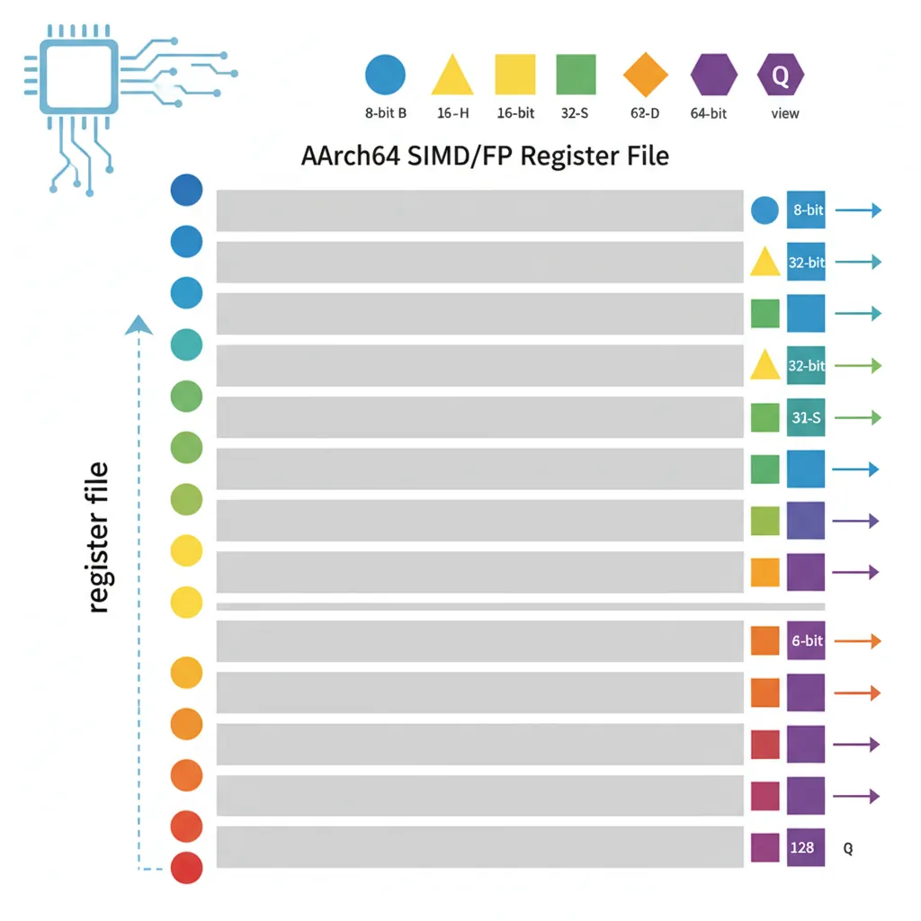
V Registers & View Widths
Each V register supports five scalar views at different widths:
| View Name | Width | Bits Used | Example | Primary Use |
|---|---|---|---|---|
| B0–B31 | 8-bit | [7:0] | MOV b0, v1.b[3] | Byte extraction |
| H0–H31 | 16-bit | [15:0] | FCVT h0, s1 | Half-precision FP (FP16) |
| S0–S31 | 32-bit | [31:0] | FADD s0, s1, s2 | Single-precision FP (float) |
| D0–D31 | 64-bit | [63:0] | FMUL d0, d1, d2 | Double-precision FP (double) |
| Q0–Q31 | 128-bit | [127:0] | LDP q0, q1, [x0] | Full-width SIMD operations |
// Scalar floating-point views (all aliased to V0)
    FMOV  s0, #1.0           // V0[31:0] = 1.0 (single-precision)
    FCVT  d1, s0              // V1[63:0] = convert 1.0f to double
    FCVT  h2, s0              // V2[15:0] = convert 1.0f to half-precision
    LDR   q3, [x0]           // V3[127:0] = load 128 bits from memory

    // IMPORTANT: writing to S0 clears V0[127:32]
    // Writing to D0 clears V0[127:64]
// Writing to Q0 uses the full 128 bitsScalar FP: S, D, H Views
Scalar floating-point instructions use the S (32-bit), D (64-bit), and H (16-bit) views for standard IEEE 754 arithmetic:
// Single-precision (float) arithmetic
    FADD  s0, s1, s2          // s0 = s1 + s2
    FMUL  s3, s0, s4          // s3 = s0 * s4
    FDIV  s5, s3, s1          // s5 = s3 / s1
    FSQRT s6, s5              // s6 = sqrt(s5)
    FABS  s7, s0              // s7 = |s0|

    // Double-precision (double) arithmetic
    FADD  d0, d1, d2          // d0 = d1 + d2
    FMADD d3, d0, d1, d2      // d3 = d0 * d1 + d2 (fused multiply-add)

    // Conversion between precisions
    FCVT  d0, s1              // float → double (widen)
    FCVT  s0, d1              // double → float (narrow, may lose precision)
    FCVT  h0, s1              // float → half-precision

    // Float ↔ integer conversion
    SCVTF s0, w1              // signed int32 → float
    FCVTZS w0, s1             // float → signed int32 (truncate toward zero)
Vector Views: 8B, 16B, 4H, 8H, etc.
NEON vector instructions partition a V register into parallel lanes using the notation Vn.nT, where n is the lane count and T is the element type. The processor executes the same operation across all lanes simultaneously — true SIMD (Single Instruction, Multiple Data):
| Notation | Lane Count × Width | Total Bits | Data Type Example |
|---|---|---|---|
V0.8B | 8 × 8-bit | 64-bit (D) | Pixel channel values (RGB) |
V0.16B | 16 × 8-bit | 128-bit (Q) | Byte-level string processing |
V0.4H | 4 × 16-bit | 64-bit (D) | Audio samples (16-bit PCM) |
V0.8H | 8 × 16-bit | 128-bit (Q) | FP16 neural network inference |
V0.2S | 2 × 32-bit | 64-bit (D) | 2D coordinates (float pair) |
V0.4S | 4 × 32-bit | 128-bit (Q) | RGBA pixels, 4D vectors |
V0.2D | 2 × 64-bit | 128-bit (Q) | Complex double-precision |
// NEON vector operations — same instruction, all lanes in parallel
    ADD   v0.4s, v1.4s, v2.4s   // 4 × int32 addition (128-bit)
    FMUL  v3.4s, v4.4s, v5.4s   // 4 × float32 multiply
    ADD   v6.16b, v7.16b, v8.16b // 16 × uint8 addition

    // Load 4 floats from array; process; store back
    LDR   q0, [x0]               // Load 128 bits = 4 floats
    FMUL  v0.4s, v0.4s, v1.4s   // Multiply all 4 by scale factors
    STR   q0, [x0]               // Store 4 results back

    // Element access across lanes
    MOV   w0, v1.s[2]            // Extract lane 2 (third float) to w0
INS v0.s[0], w1 // Insert w1 into lane 0 of v0Register Width Reference Card
A quick-reference showing how the same physical 128-bit register V0 appears under different aliases:
V0 (128 bits):
┌─────────────────────────────────────────────────────────┐
│                    Q0 (128-bit)                         │
├─────────────────────────────┬───────────────────────────┤
│        D0 (64-bit)          │      (upper 64 bits)      │
├──────────────┬──────────────┼──────────────┬────────────┤
│  S0 (32-bit) │   (bits 63:32│              │            │
├──────┬───────┼──────┬───────┼──────┬───────┼──────┬─────┤
│H0 16b│      │      │       │      │       │      │     │
├───┬──┼──┬───┼──┬───┼──┬────┼──┬───┼──┬────┼──┬───┼──┬──┤
│B0 │  │  │   │  │   │  │    │  │   │  │    │  │   │  │  │
│8b │  │  │   │  │   │  │    │  │   │  │    │  │   │  │  │
└───┴──┴──┴───┴──┴───┴──┴────┴──┴───┴──┴────┴──┴───┴──┴──┘

Vector views of V0:
  V0.16B = [b15 b14 b13 b12 b11 b10 b9  b8  b7  b6  b5  b4  b3  b2  b1  b0]
  V0.8H  = [  h7    h6    h5    h4    h3    h2    h1    h0  ]
  V0.4S  = [      s3          s2          s1          s0    ]
  V0.2D  = [            d1                      d0          ]
Exercises
int count, (b) char *ptr, (c) float temperature, (d) unsigned long flags, (e) double result, (f) short voltage. What instruction would you use to load each from memory?
array[i] where array is a pointer in X0 and i is a 32-bit unsigned index in W1, for each case: (a) uint8_t array[], (b) uint32_t array[], (c) uint64_t array[]. How does the shift amount in the register offset relate to sizeof(element)?
ARM Register Map Generator
Generate a custom AArch64 register reference document with your annotations. Download as Word, Excel, or PDF.
Conclusion & Next Steps
In this article, we've mapped out the entire AArch64 register and memory-access landscape:
- 31 GP registers (X0–X30) with 32-bit W aliases, zero-extension on W writes, and the elegant XZR/WZR zero register
- System registers accessed via MRS/MSR — NZCV condition flags, FPSR/FPCR floating-point control, PSTATE fields, and the entire system configuration hierarchy
- Five addressing modes — base+immediate, register offset with extend/shift, pre-index, post-index, and PC-relative (ADR/ADRP) for position-independent code
- Load/Store instructions covering every width from byte to doubleword, sign-extension loads, exclusive monitors for atomics, and acquire/release semantics for lock-free programming
- LDP/STP pair instructions — the canonical prologue/epilogue pattern and their micro-architectural performance advantage
- 32 SIMD/FP registers (V0–V31) with scalar views (B/H/S/D/Q) and vector lane configurations for NEON parallel processing
With this foundation in place, you now have the vocabulary to read and understand any AArch64 disassembly. In Part 4, we'll put these registers to work with the full arithmetic and bit-manipulation instruction set — ADD/SUB with carry chains, multiply/divide, bitfield extraction and insertion, count-leading-zeros, and the powerful conditional select family.