Introduction & Cortex-M Profile
ARM Assembly Mastery
Architecture History & Core Concepts
ARMv1→v9, RISC philosophy, profilesARM32 Instruction Set Fundamentals
ARM vs Thumb, registers, CPSR, barrel shifterAArch64 Registers, Addressing & Data Movement
X/W regs, addressing modes, load/store pairsArithmetic, Logic & Bit Manipulation
ADD/SUB, bitfield extract/insert, CLZBranching, Loops & Conditional Execution
Branch types, link register, jump tablesStack, Subroutines & AAPCS
Calling conventions, prologue/epilogueMemory Model, Caches & Barriers
Weak ordering, DMB/DSB/ISB, TLBNEON & Advanced SIMD
Vector ops, intrinsics, media processingSVE & SVE2 Scalable Vector Extensions
Predicate regs, gather/scatter, HPC/MLFloating-Point & VFP Instructions
IEEE-754, scalar FP, rounding modesException Levels, Interrupts & Vector Tables
EL0–EL3, GIC, fault debuggingMMU, Page Tables & Virtual Memory
Stage-1 translation, permissions, huge pagesTrustZone & ARM Security Extensions
Secure monitor, world switching, TF-ACortex-M Assembly & Bare-Metal Embedded
NVIC, SysTick, linker scripts, low-powerCortex-A System Programming & Boot
EL3→EL1 transitions, MMU setup, PSCIApple Silicon & macOS ABI
ARM64e PAC, Mach-O, dyld, perf countersInline Assembly, GCC/Clang & C Interop
Constraints, clobbers, compiler interactionPerformance Profiling & Micro-Optimization
Pipeline hazards, PMU, benchmarkingReverse Engineering & ARM Binary Analysis
ELF, disassembly, CFR, iOS/Android quirksBuilding a Bare-Metal OS Kernel
Bootloader, UART, scheduler, context switchARM Microarchitecture Deep Dive
OOO pipelines, reorder buffers, branch predictVirtualization Extensions
EL2 hypervisor, stage-2 translation, KVMDebugging & Tooling Ecosystem
GDB, OpenOCD/JTAG, ETM/ITM, QEMULinkers, Loaders & Binary Format Internals
ELF deep dive, relocations, PIC, crt0Cross-Compilation & Build Systems
GCC/Clang toolchains, CMake, firmware genARM in Real Systems
Android, FreeRTOS/Zephyr, U-Boot, TF-ASecurity Research & Exploitation
ASLR, PAC attacks, ROP/JOP, kernel exploitEmerging ARMv9 & Future Directions
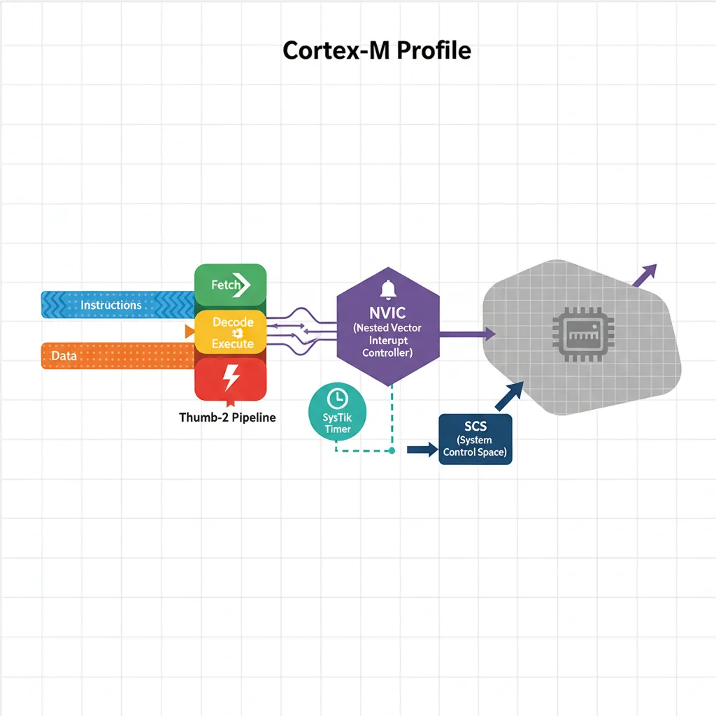
MTE, SME, confidential compute, AI accelCortex-M cores (M0, M0+, M3, M4, M7, M23, M33, M55, M85) are Harvard-architecture processors without an MMU, running exclusively in Thumb or Thumb-2 state. There is no AArch64, no EL system, and no separate secure monitor — though Cortex-M23/M33/M55 add a simplified TrustZone-M for IoT security. The entire exception and interrupt model fits in a 4 KB region-of-interest: the System Control Space (SCS) at 0xE000E000.
Cortex-M Family Comparison
The Cortex-M family spans from ultra-low-power IoT sensors (M0) to high-performance DSP/ML edge processors (M55/M85). Each core builds on the previous generation, adding pipeline stages, instruction set extensions, and security features. The table below provides a side-by-side comparison of key specifications to help you choose the right core for your application:
| Core | Architecture | Pipeline | ISA | FPU | DSP | TrustZone-M | Typical Use |
|---|---|---|---|---|---|---|---|
| Cortex-M0 | ARMv6-M | 3-stage | Thumb (subset) | ✗ | ✗ | ✗ | Ultra-low-power sensors, simple GPIO |
| Cortex-M0+ | ARMv6-M | 2-stage | Thumb (subset) | ✗ | ✗ | ✗ | Lowest power, wearables, battery tags |
| Cortex-M3 | ARMv7-M | 3-stage | Thumb-2 (full) | ✗ | ✗ | ✗ | General-purpose MCU, industrial control |
| Cortex-M4 | ARMv7E-M | 3-stage | Thumb-2 + DSP | SP (opt.) | ✓ | ✗ | Motor control, audio, sensor fusion |
| Cortex-M7 | ARMv7E-M | 6-stage (dual-issue) | Thumb-2 + DSP | SP + DP | ✓ | ✗ | High-perf embedded, automotive, graphics |
| Cortex-M23 | ARMv8-M Baseline | 2-stage | Thumb (subset) | ✗ | ✗ | ✓ | Secure IoT endpoints, smart cards |
| Cortex-M33 | ARMv8-M Mainline | 3-stage | Thumb-2 + DSP | SP (opt.) | ✓ | ✓ | Secure MCU, NB-IoT, BLE SoCs |
| Cortex-M55 | ARMv8.1-M | 4-stage | Thumb-2 + Helium (MVE) | SP + DP | ✓ | ✓ | ML inference at edge, keyword spotting |
| Cortex-M85 | ARMv8.1-M | 7-stage (dual-issue) | Thumb-2 + Helium (MVE) | SP + DP | ✓ | ✓ | High-perf secure ML, advanced automotive |
Thumb-2 Instruction Set
16-bit vs 32-bit Encoding
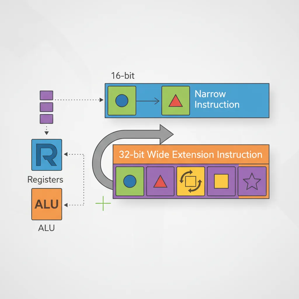
Thumb-2 mixes 16-bit and 32-bit encodings in the same instruction stream. The 16-bit subset covers the most common operations (MOV, ADD, LDR, STR, push/pop, branches) for code density. The 32-bit Thumb-2 extensions add the full barrel-shifter operands, more registers, wider immediates, multiply-accumulate, and SIMD/DSP instructions. The assembler selects the shorter encoding automatically unless forced with the .W (wide) or .N (narrow) suffixes.
// 16-bit Thumb (narrow) — most efficient for Cortex-M0
MOVS  r0, #42          // 16-bit: set r0=42, update flags
ADDS  r1, r0, #1       // 16-bit: r1 = r0+1, flags updated

// 32-bit Thumb-2 (wide) — needed for wider immediates
MOVW  r0, #0xBEEF      // 32-bit: load 16-bit immediate
MOVT  r0, #0xDEAD      // 32-bit: load upper 16 bits → r0=0xDEADBEEF

// Barrel shifter in 32-bit encoding (not available in 16-bit)
ADD.W r2, r1, r0, LSL #3   // r2 = r1 + (r0 << 3)

// High-register MOV (32-bit) to transfer between hi and lo regs
MOV   r8, r0           // 16-bit encoding for hi-reg mov (special form)
IT Block Conditional Execution
// IT block: up to 4 conditionally-executed Thumb instructions
// Syntax: IT[T|E][T|E][T|E] cond
// T = Then (execute if cond true), E = Else (execute if cond false)
CMP   r0, #0
ITE   EQ               // If EQ: execute next (Then), else execute after (Else)
MOVEQ r1, #1           // r1=1 if r0==0
MOVNE r1, #0           // r1=0 if r0!=0

// 3-condition example:
CMP  r2, r3
ITTEE GT               // GT: Then Then, else Else Else
MOVGT r4, r2
ADDGT r5, r2, #1
MOVLE r4, r3
ADDLE r5, r3, #1

// Note: IT blocks are deprecated in Thumb-2 for Cortex-M7+ (ITSTATE complications)
// Prefer conditional branches for clarity in new code
Cortex-M Vector Table
The 16 System Exceptions
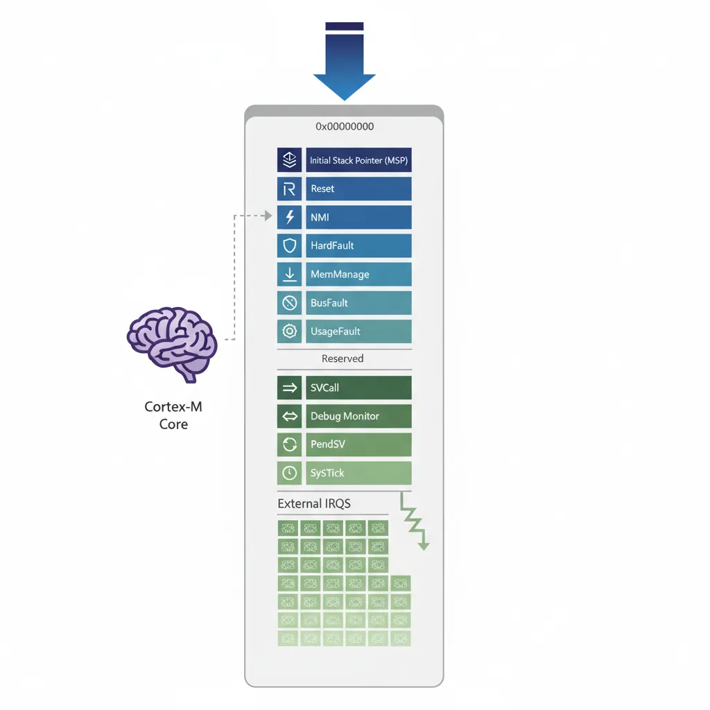
Before the external IRQs, the Cortex-M vector table reserves entries 0–15 for system exceptions. Entry 0 is the initial stack pointer — not an exception handler, but it shares the vector table space. Entries 1–15 are the 15 exception handlers, plus the stack pointer entry, giving 16 system-defined entries total. Understanding each one is essential for writing reliable bare-metal firmware:
Cortex-M System Exception Reference (Entries 0–15)
| # | Offset | Exception | Priority | Description |
|---|---|---|---|---|
| 0 | 0x00 | Initial MSP | — | Main Stack Pointer reset value (not a handler) |
| 1 | 0x04 | Reset | −3 (fixed) | Power-on / warm reset — highest priority, non-maskable |
| 2 | 0x08 | NMI | −2 (fixed) | Non-Maskable Interrupt — typically watchdog or voltage monitor |
| 3 | 0x0C | HardFault | −1 (fixed) | Catch-all for faults that are not handled or not enabled |
| 4 | 0x10 | MemManage | Configurable | MPU violation or instruction fetch from non-executable region |
| 5 | 0x14 | BusFault | Configurable | Bus error during data/instruction access (e.g., invalid address) |
| 6 | 0x18 | UsageFault | Configurable | Undefined instruction, unaligned access, divide-by-zero |
| 7–10 | 0x1C–0x28 | Reserved | — | Reserved by ARM — must be zero in vector table |
| 11 | 0x2C | SVCall | Configurable | Supervisor Call via SVC instruction (RTOS system calls) |
| 12 | 0x30 | Debug Monitor | Configurable | Software debug events when not halting the core |
| 13 | 0x34 | Reserved | — | Reserved by ARM — must be zero |
| 14 | 0x38 | PendSV | Configurable | Pendable Service Call — used by RTOS for context switching |
| 15 | 0x3C | SysTick | Configurable | System Tick Timer — RTOS tick, periodic scheduling interrupt |
Reset Handler & Stack Setup
The Cortex-M vector table starts at address 0x00000000 (or the address in VTOR). Entry 0 is the initial stack pointer value (loaded into MSP at reset). Entry 1 is the reset handler address. All vector entries use odd addresses (bit[0]=1) to indicate Thumb mode. The hardware never executes ARM state code on Cortex-M.
// Cortex-M4 minimal vector table (GAS syntax)
    .section ".vectors", "a", %progbits
    .type  vector_table, %object
vector_table:
    .word  _stack_top          // 0x00: Initial MSP value (from linker)
    .word  reset_handler + 1   // 0x04: Reset (bit[0]=1 for Thumb)
    .word  nmi_handler + 1     // 0x08: NMI
    .word  hardfault_handler + 1 // 0x0C: HardFault
    .word  memmanage_handler + 1 // 0x10: MemManage
    .word  busfault_handler + 1  // 0x14: BusFault
    .word  usagefault_handler + 1// 0x18: UsageFault
    .word  0, 0, 0, 0          // 0x1C-0x28: Reserved
    .word  svc_handler + 1     // 0x2C: SVCall
    .word  0, 0                // 0x30-0x34: Debug / Reserved
    .word  pendsv_handler + 1  // 0x38: PendSV (RTOS context switch)
    .word  systick_handler + 1 // 0x3C: SysTick
    // External interrupts (IRQ0..N) follow from 0x40 onward
    .word  uart_irq_handler + 1
    .word  tim2_irq_handler + 1
    .size  vector_table, . - vector_table

// Reset handler: copy .data, zero .bss, call main
    .section ".text"
    .thumb_func
    .global reset_handler
reset_handler:
    LDR   r0, =_data_load      // Source: Flash
    LDR   r1, =_data_start     // Destination: SRAM
    LDR   r2, =_data_end
copy_data:
    CMP   r1, r2
    BGE   zero_bss
    LDR   r3, [r0], #4
    STR   r3, [r1], #4
    B     copy_data
zero_bss:
    LDR   r1, =_bss_start
    LDR   r2, =_bss_end
    MOVS  r3, #0
clear_bss:
    CMP   r1, r2
    BGE   call_main
    STR   r3, [r1], #4
    B     clear_bss
call_main:
    BL    main
    B     .                    // Infinite loop if main returns
HardFault / MemManage / BusFault
// HardFault handler: inspect stacked frame for diagnostic
    .thumb_func
hardfault_handler:
    // Determine which stack was active: MSP or PSP
    TST   lr, #4               // EXC_RETURN[2]: 0=MSP, 1=PSP
    ITE   EQ
    MRSEQ r0, MSP              // r0 = pointer to exception frame
    MRSNE r0, PSP
    // Exception frame (hardware push): r0,r1,r2,r3,r12,lr,pc,xpsr
    LDR   r1, [r0, #24]        // Stacked PC (faulting instruction)
    LDR   r2, =0xE000ED28      // CFSR (Configurable Fault Status Register)
    LDR   r3, [r2]             // Read CFSR: MemManage/BusFault/UsageFault flags
    B     .                    // Halt (replace with UART debug in production)
NVIC — Nested Vectored Interrupt Controller
Priority Configuration
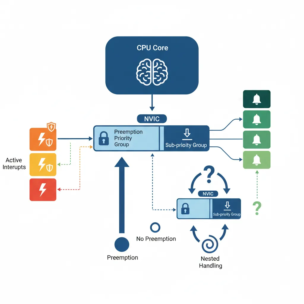
The NVIC supports up to 240 external interrupts (IRQs) with configurable priorities. Priority width varies by implementation (typically 3–8 bits, with higher numerical value = lower priority). Cortex-M3/M4/M7 support preemption grouping via AIRCR.PRIGROUP: this splits the priority byte into group priority (preemption) and sub-priority (tie-breaking) bits. Lower group priority number = higher precedence and can preempt running handlers.
// NVIC register base: 0xE000E100
// Enable IRQ #37 (e.g., USART2 on STM32)
// NVIC_ISER[1] = 1 << (37 - 32) = 1 << 5 = 0x20
LDR  r0, =0xE000E104       // NVIC_ISER1
MOV  r1, #(1 << 5)
STR  r1, [r0]              // Enable USART2 interrupt

// Set priority of IRQ 37 to 0x40 (moderate priority)
LDR  r0, =0xE000E425       // NVIC_IPR9 (IRQ 37 is in byte 1 of IPR9)
LDR  r1, [r0]
BIC  r1, r1, #(0xFF << 8)  // Clear byte 1
ORR  r1, r1, #(0x40 << 8)  // Set priority 0x40
STR  r1, [r0]

// Disable IRQ 37
LDR  r0, =0xE000E184       // NVIC_ICER1
MOV  r1, #(1 << 5)
STR  r1, [r0]
Writing ISRs in Assembly
// UART RX ISR — read received byte, store to ring buffer
// Cortex-M hardware auto-pushes: r0,r1,r2,r3,r12,lr,pc,xpsr
// EXC_RETURN in LR tells hardware what to restore on exit
    .thumb_func
    .global uart_irq_handler
uart_irq_handler:
    PUSH  {r4-r7, lr}          // Save callee-saved regs + LR(EXC_RETURN)

    LDR   r0, =USART2_BASE
    LDR   r1, [r0, #0x00]      // USART_SR: check RXNE flag
    TST   r1, #(1 << 5)        // RXNE (bit 5)?
    BEQ   uart_done

    LDR   r2, [r0, #0x04]      // USART_DR: read received byte (clears RXNE)
    UXTB  r2, r2                // Extract byte

    // Store in ring buffer (call C function)
    BL    ring_buffer_put       // r0=byte already happens via r2, adjust as needed

uart_done:
    POP   {r4-r7, pc}           // POP LR into PC — return from interrupt
SysTick Timer
// SysTick registers (addresses 0xE000E010-0xE000E01F)
// SYST_CSR  = 0xE000E010: Control and Status
// SYST_RVR  = 0xE000E014: Reload Value
// SYST_CVR  = 0xE000E018: Current Value
// SYST_CALIB= 0xE000E01C: Calibration

// Configure SysTick for 1 ms tick at 72 MHz core clock
// Reload value = (72,000,000 / 1000) - 1 = 71999
LDR  r0, =0xE000E010           // SYST_CSR
LDR  r1, =0xE000E014           // SYST_RVR
LDR  r2, =0xE000E018           // SYST_CVR

MOV  r3, #71999
STR  r3, [r1]                  // Set reload value
MOV  r3, #0
STR  r3, [r2]                  // Clear current value (any write resets it)

// CSR: ENABLE=1, TICKINT=1 (generate interrupt), CLKSOURCE=1 (core clock)
MOV  r3, #0x7
STR  r3, [r0]                  // Start SysTick, enable interrupt

// SysTick ISR (fires every 1 ms)
    .thumb_func
    .global systick_handler
systick_handler:
    PUSH {lr}
    BL   os_tick               // RTOS tick increment
    POP  {pc}
Peripheral Register Access (GPIO & MMIO)
Every Cortex-M peripheral is memory-mapped. GPIO ports, UART controllers, ADC converters, and DMA engines are accessed by reading and writing 32-bit registers at fixed addresses. The vendor datasheet gives register offsets from each peripheral's base address. The key discipline is: read-modify-write (load register, mask bits, OR in new value, store back) to avoid clobbering other fields in the same register.
GPIO Configuration — Blinking an LED
// STM32F4 — Toggle PA5 (LED on Nucleo-F446RE)
// 1. Enable GPIOA clock (RCC AHB1ENR, bit 0)
    LDR   r0, =0x40023830      // RCC_AHB1ENR
    LDR   r1, [r0]
    ORR   r1, r1, #(1 << 0)    // GPIOAEN = 1
    STR   r1, [r0]

// 2. Set PA5 as output (GPIOA_MODER bits [11:10] = 01)
    LDR   r0, =0x40020000      // GPIOA_MODER
    LDR   r1, [r0]
    BIC   r1, r1, #(3 << 10)   // Clear bits [11:10]
    ORR   r1, r1, #(1 << 10)   // Set bit 10 → output mode
    STR   r1, [r0]

// 3. Toggle LED via BSRR (atomic set/reset — no read-modify-write needed)
    LDR   r0, =0x40020018      // GPIOA_BSRR
    MOV   r1, #(1 << 5)        // Set PA5 high (bits [15:0] = set)
    STR   r1, [r0]
    // ... delay ...
    MOV   r1, #(1 << 21)       // Reset PA5 low (bits [31:16] = reset)
    STR   r1, [r0]
Common MMIO Patterns
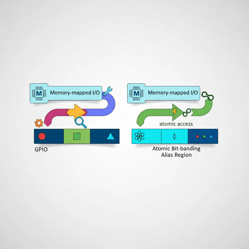
volatile semantics — in assembly this is natural since every LDR/STR hits memory, but in C wrappers, mark peripheral pointers volatile. (2) Some registers are write-only (e.g., BSRR) — reading them returns zero or undefined data. (3) Bit-banding (Cortex-M3/M4) maps each bit to a word address in the alias region, enabling atomic single-bit set/clear without read-modify-write: alias_addr = 0x42000000 + (byte_offset × 32) + (bit × 4).
// Bit-banding example: set bit 5 of GPIOA_ODR atomically
// GPIOA_ODR = 0x40020014, bit 5
// Offset from peripheral base 0x40000000 = 0x00020014
// Alias = 0x42000000 + (0x20014 × 32) + (5 × 4) = 0x42400294
    LDR   r0, =0x42400294   // Bit-band alias for PA5
    MOV   r1, #1
STR r1, [r0] // Atomic set PA5 — no RMW race conditionCase Study: STM32 Smart Thermostat — From Prototype to Product
A startup built an IoT smart thermostat on an STM32F401 (Cortex-M4, 84 MHz, 256 KB Flash, 64 KB SRAM). The firmware was entirely bare-metal assembly + C, with no RTOS, to minimize power consumption for battery operation.
Architecture decisions: The NVIC was configured with 4 priority groups — the ADC conversion-complete ISR (priority 0, highest) sampled the temperature sensor every 100 ms via DMA. The UART TX ISR (priority 2) sent readings to a Bluetooth module. SysTick at 1 kHz drove the PID control loop. A WFE sleep loop in the main thread dropped power to 12 μA between samples. GPIO PA5 drove the relay controlling the HVAC system via BSRR atomic writes.
Key insight: By using bit-banding for all GPIO flag checks, the team eliminated race conditions between the main loop and ISRs without disabling interrupts. The total firmware size was 18 KB — fitting in the smallest STM32 variant for the production run, reducing per-unit BOM cost by $0.40.
Linker Script & Memory Map
Flash / SRAM Section Layout
A typical STM32 linker script defines MEMORY regions for Flash (origin 0x08000000) and SRAM (origin 0x20000000). Sections map as: .vectors and .text → Flash; .data (initialised variables) → LMA in Flash, VMA in SRAM (copied by startup); .bss (zero-initialised) → SRAM only; .stack → top of SRAM. Export symbols (_data_load, _data_start, _data_end, _bss_start, _bss_end, _stack_top) that the startup assembly uses.
Startup Code (crt0)
// Minimal linker script excerpt (GNU LD)
// MEMORY {
//   FLASH (rx)  : ORIGIN = 0x08000000, LENGTH = 512K
//   RAM   (rwx) : ORIGIN = 0x20000000, LENGTH = 128K
// }
// SECTIONS {
//   .vectors : { *(.vectors) } > FLASH
//   .text    : { *(.text*) }   > FLASH
//   .data    : { *(.data*) }   > RAM AT> FLASH  /* LMA in Flash, VMA in RAM */
//   .bss     : { *(.bss*) }    > RAM
//   _stack_top = ORIGIN(RAM) + LENGTH(RAM);
// }

// Assembly startup (after vector table copy and BSS clear):
    .text
    .thumb_func
    .weak  _start
    .global _start
_start:
    LDR   sp, =_stack_top      // Set MSP (redundant if vector table entry is correct)
    BL    SystemInit            // Optional: clock/PLL init
    BL    main
    B     .
Low-Power Modes (WFI / WFE)
// WFI — Wait For Interrupt: halt CPU until any enabled interrupt fires
// Used by RTOS idle task; wakes on any unmasked pending interrupt
idle_loop:
    WFI                        // Freeze pipeline; resume on next interrupt
    B    idle_loop

// WFE — Wait For Event: halt until event register set or interrupt
// More flexible: also wakes on SEV (Send Event) from another CPU
// Or on the stacked-event bit from a previous interrupt during low-power
sleep_loop:
    SEV                        // Set own event register first (clear stale event)
    WFE                        // Clear event register; if already set: fall through
    WFE                        // Real sleep: wait for external event or interrupt
    B    sleep_loop

// Cortex-M4 SCB SCR register: enable SLEEPDEEP for deep sleep (Stop/Standby)
LDR  r0, =0xE000ED10           // SCB_SCR
LDR  r1, [r0]
ORR  r1, r1, #(1 << 2)        // SLEEPDEEP=1
STR  r1, [r0]
WFI // Enter deep sleep (STOP mode on STM32)Hands-On Exercises
Exercise: SOS Blink Pattern in Assembly
Write a Cortex-M4 assembly program that blinks an LED on PA5 in the SOS Morse code pattern: three short flashes (200 ms), three long flashes (600 ms), three short flashes, then a 2-second pause. Use a delay loop based on the core clock frequency (assume 72 MHz). Structure the code with subroutines: short_blink, long_blink, and delay_ms (parameter in r0). Configure GPIOA via RCC and MODER registers, then use BSRR for atomic set/reset.
Bonus: Replace the busy-wait delay loop with SysTick interrupts — set a volatile ms_ticks counter and have the main loop poll it for timing accuracy.
Exercise: Multi-Priority NVIC Configuration
Configure the NVIC for three interrupt sources on an STM32F4: (1) EXTI0 (button press on PA0) at priority 0x00 (highest — debounce via counter), (2) TIM2 overflow at priority 0x40 (medium — toggling PB0 LED), and (3) USART2 RXNE at priority 0x80 (lowest — buffering incoming bytes). Write each ISR in Thumb assembly. Demonstrate preemption: while the USART2 ISR is running, trigger EXTI0 and verify it preempts by toggling a different GPIO pin.
Verification: Use a logic analyser or oscilloscope to observe the GPIO toggles and confirm that higher-priority interrupts preempt lower-priority handlers with correct tail-chaining on return.
Exercise: Custom Linker Script + Startup Assembly
Write a complete GNU LD linker script for an STM32F446RE (512 KB Flash at 0x08000000, 128 KB SRAM at 0x20000000). Define sections: .vectors → Flash (first 0x200 bytes), .text → Flash, .rodata → Flash, .data → SRAM (AT> FLASH), .bss → SRAM. Export all required symbols. Then write a startup assembly file (startup.s) that: (1) defines the vector table with all 16 system exceptions + 6 IRQ handlers, (2) copies .data from Flash to SRAM, (3) zeros .bss, (4) calls SystemInit and main. Build with arm-none-eabi-gcc -T linker.ld -nostdlib startup.s main.c -o firmware.elf.
Bonus: Add a .config section in Flash for non-volatile settings, and a .stack section with a guard word (0xDEADBEEF) to detect stack overflows at runtime.
Embedded Project Planner
ARM Embedded Project Planner
Plan your Cortex-M bare-metal project. Specify MCU, peripherals, interrupts, and firmware architecture. Download as Word, Excel, or PDF.
All data stays in your browser — nothing is uploaded.
Conclusion & Next Steps
We built a complete Cortex-M bare-metal environment from the ground up: Thumb-2 instruction encodings (16-bit vs 32-bit, IT blocks for conditional execution), the vector table with reset handler initialising .data and .bss, NVIC interrupt enable/priority configuration with preemption groups, ISR writing with hardware auto-push/pop, SysTick for RTOS tick generation, GPIO and peripheral register access via MMIO and bit-banding, linker script section layout, startup assembly (crt0), and WFI/WFE low-power patterns for battery-powered IoT devices.