Microcontrollers for Robotics
Robotics & Automation Mastery
Introduction to Robotics
History, types, DOF, architectures, mechatronics, ethicsSensors & Perception Systems
Encoders, IMUs, LiDAR, cameras, sensor fusion, Kalman filters, SLAMActuators & Motion Control
DC/servo/stepper motors, hydraulics, drivers, gear systemsKinematics (Forward & Inverse)
DH parameters, transformations, Jacobians, workspace analysisDynamics & Robot Modeling
Newton-Euler, Lagrangian, inertia, friction, contact modelingControl Systems & PID
PID tuning, state-space, LQR, MPC, adaptive & robust controlEmbedded Systems & Microcontrollers
Arduino, STM32, RTOS, PWM, serial protocols, FPGARobot Operating Systems (ROS)
ROS2, nodes, topics, Gazebo, URDF, navigation stacksComputer Vision for Robotics
Calibration, stereo vision, object recognition, visual SLAMAI Integration & Autonomous Systems
ML, reinforcement learning, path planning, swarm roboticsHuman-Robot Interaction (HRI)
Cobots, gesture/voice control, safety standards, social roboticsIndustrial Robotics & Automation
PLC, SCADA, Industry 4.0, smart factories, digital twinsMobile Robotics
Wheeled/legged robots, autonomous vehicles, drones, marine roboticsSafety, Reliability & Compliance
Functional safety, redundancy, ISO standards, cybersecurityAdvanced & Emerging Robotics
Soft robotics, bio-inspired, surgical, space, nano-roboticsSystems Integration & Deployment
HW/SW co-design, testing, field deployment, lifecycleRobotics Business & Strategy
Startups, product-market fit, manufacturing, go-to-marketComplete Robotics System Project
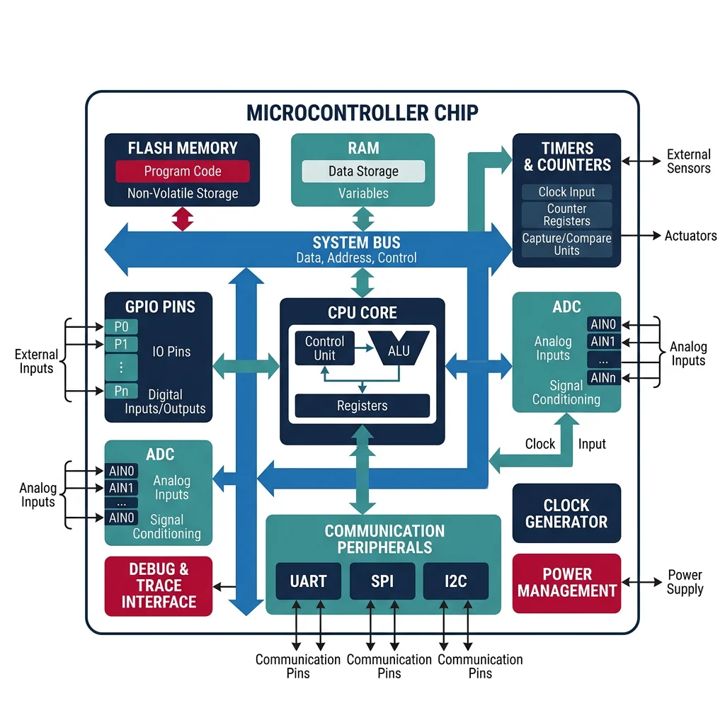
Autonomous rover, pick-and-place arm, delivery robot, swarm simEvery robot has a brain — not a laptop or server, but a small, dedicated microcontroller (MCU) running code in real time, directly controlling motors, reading sensors, and making decisions in microseconds. A microcontroller is a complete computer on a single chip: processor (CPU), memory (RAM + Flash), and peripherals (timers, ADCs, communication interfaces) all integrated together.
Arduino Platform
Arduino is the gateway to embedded robotics. Its ecosystem combines simple hardware boards with an accessible C/C++ framework, making it perfect for prototyping and education.
| Board | MCU | Clock | Flash | RAM | GPIO | Robotics Use |
|---|---|---|---|---|---|---|
| Arduino Uno R3 | ATmega328P | 16 MHz | 32 KB | 2 KB | 20 | Basic robots, servo control, sensor reading |
| Arduino Mega 2560 | ATmega2560 | 16 MHz | 256 KB | 8 KB | 54 | Complex robots with many I/O channels |
| Arduino Due | SAM3X8E (ARM) | 84 MHz | 512 KB | 96 KB | 54 | Higher-performance control loops |
| ESP32 | Xtensa LX6 | 240 MHz | 4 MB | 520 KB | 34 | Wi-Fi/BLE robots, IoT integration |
| Teensy 4.1 | i.MX RT1062 (ARM) | 600 MHz | 8 MB | 1 MB | 55 | High-speed sensor fusion, audio processing |
// Arduino: Basic robot motor control with encoder feedback
// Reads encoder, runs PID, controls motor via PWM

// Pin definitions
const int MOTOR_PWM = 9;     // PWM output to motor driver
const int MOTOR_DIR = 8;     // Direction pin
const int ENCODER_A = 2;     // Encoder channel A (interrupt-capable)
const int ENCODER_B = 3;     // Encoder channel B

// PID parameters
float Kp = 2.0, Ki = 0.5, Kd = 0.1;
float setpoint = 1000;  // target encoder count

volatile long encoderCount = 0;
float integral = 0, prevError = 0;
unsigned long prevTime = 0;

// Interrupt service routine for encoder
void encoderISR() {
    if (digitalRead(ENCODER_B) == HIGH)
        encoderCount++;
    else
        encoderCount--;
}

void setup() {
    Serial.begin(115200);
    pinMode(MOTOR_PWM, OUTPUT);
    pinMode(MOTOR_DIR, OUTPUT);
    pinMode(ENCODER_A, INPUT_PULLUP);
    pinMode(ENCODER_B, INPUT_PULLUP);

    // Attach interrupt on rising edge of channel A
    attachInterrupt(digitalPinToInterrupt(ENCODER_A), encoderISR, RISING);

    prevTime = micros();
}

void loop() {
    // Calculate dt in seconds
    unsigned long now = micros();
    float dt = (now - prevTime) / 1000000.0;
    prevTime = now;

    // PID computation
    float error = setpoint - encoderCount;
    integral += error * dt;
    integral = constrain(integral, -500, 500);  // anti-windup
    float derivative = (error - prevError) / dt;
    float output = Kp * error + Ki * integral + Kd * derivative;
    prevError = error;

    // Apply to motor
    int pwmVal = constrain(abs((int)output), 0, 255);
    digitalWrite(MOTOR_DIR, output >= 0 ? HIGH : LOW);
    analogWrite(MOTOR_PWM, pwmVal);

    // Debug output at 10 Hz
    static unsigned long lastPrint = 0;
    if (now - lastPrint > 100000) {
        Serial.print("Pos: "); Serial.print(encoderCount);
        Serial.print("  Err: "); Serial.print(error);
        Serial.print("  PWM: "); Serial.println(pwmVal);
        lastPrint = now;
    }

    delayMicroseconds(100);  // ~10kHz control loop
}
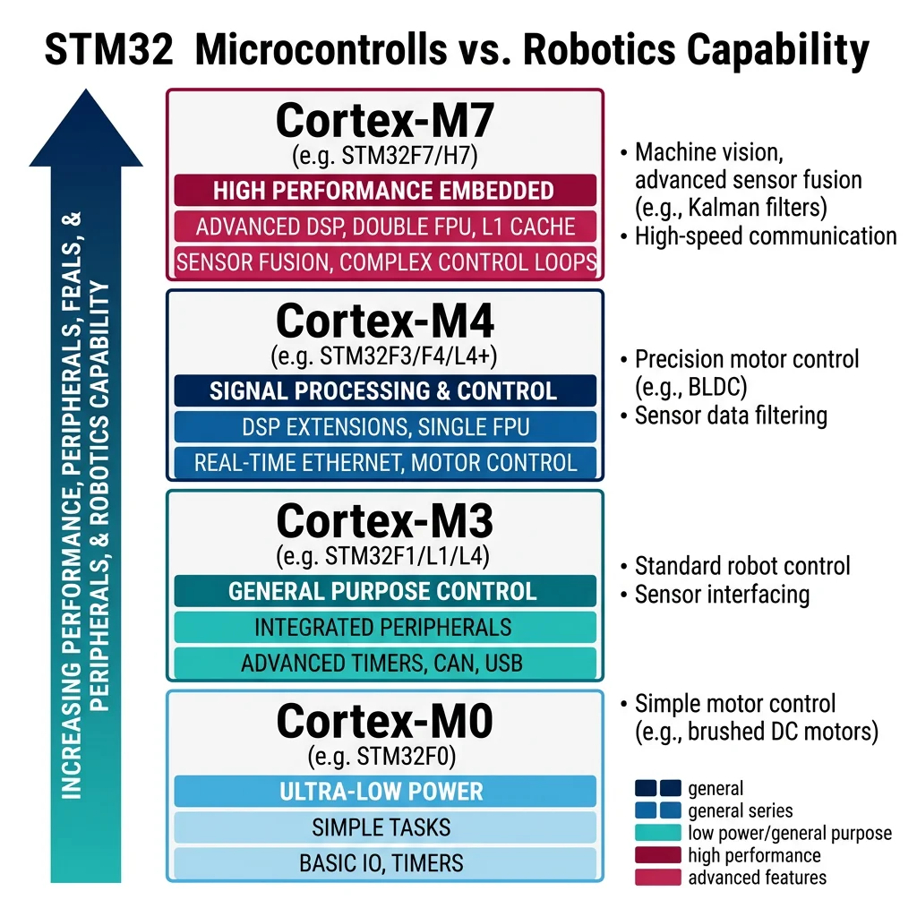
STM32 Family
When projects outgrow Arduino, the STM32 family (by STMicroelectronics) is the professional choice. Based on ARM Cortex-M cores, STM32 chips offer dramatically more processing power, peripherals, and features for serious robotics applications.
| Series | Core | Clock | Typical Use |
|---|---|---|---|
| STM32F0 | Cortex-M0 | 48 MHz | Simple sensor nodes, cost-sensitive designs |
| STM32F1 | Cortex-M3 | 72 MHz | General-purpose motor control, basic robots |
| STM32F4 | Cortex-M4F | 168 MHz | DSP-capable — sensor fusion, audio, PID loops |
| STM32F7 | Cortex-M7 | 216 MHz | High-performance control, image processing |
| STM32H7 | Cortex-M7 | 480 MHz | Multi-axis CNC, advanced drone flight controllers |
// STM32 HAL: High-performance motor control with hardware timer PWM
// Runs PID at 10 kHz using timer interrupt

#include "stm32f4xx_hal.h"

// Global variables
volatile int32_t encoder_count = 0;
volatile float pid_output = 0;
float Kp = 3.0f, Ki = 1.0f, Kd = 0.05f;
float target_velocity = 500.0f;  // RPM
float integral = 0, prev_error = 0;

// Timer interrupt callback — runs every 100us (10 kHz)
void HAL_TIM_PeriodElapsedCallback(TIM_HandleTypeDef *htim) {
    if (htim->Instance == TIM6) {
        // Read encoder via hardware timer (TIM3 in encoder mode)
        int32_t current_count = __HAL_TIM_GET_COUNTER(&htim3);
        float velocity = (current_count - encoder_count) * 10000.0f / 4096.0f * 60.0f; // RPM
        encoder_count = current_count;

        // PID control
        float dt = 0.0001f;  // 100us
        float error = target_velocity - velocity;
        integral += error * dt;
        if (integral > 100) integral = 100;     // anti-windup
        if (integral < -100) integral = -100;
        float derivative = (error - prev_error) / dt;
        pid_output = Kp * error + Ki * integral + Kd * derivative;
        prev_error = error;

        // Set PWM duty cycle via hardware timer (TIM1)
        uint16_t pwm = (uint16_t)fmaxf(0, fminf(pid_output, 999));
        __HAL_TIM_SET_COMPARE(&htim1, TIM_CHANNEL_1, pwm);
    }
}

int main(void) {
    HAL_Init();
    SystemClock_Config();  // Configure 168 MHz clock
    MX_GPIO_Init();
    MX_TIM1_Init();  // PWM output timer (20 kHz)
    MX_TIM3_Init();  // Encoder input timer
    MX_TIM6_Init();  // PID loop timer (10 kHz interrupt)

    HAL_TIM_PWM_Start(&htim1, TIM_CHANNEL_1);    // Start PWM
    HAL_TIM_Encoder_Start(&htim3, TIM_CHANNEL_ALL); // Start encoder
    HAL_TIM_Base_Start_IT(&htim6);  // Start PID interrupt

    while (1) {
        // Main loop handles non-real-time tasks
        // (communication, logging, state machine, etc.)
        HAL_Delay(10);
    }
}
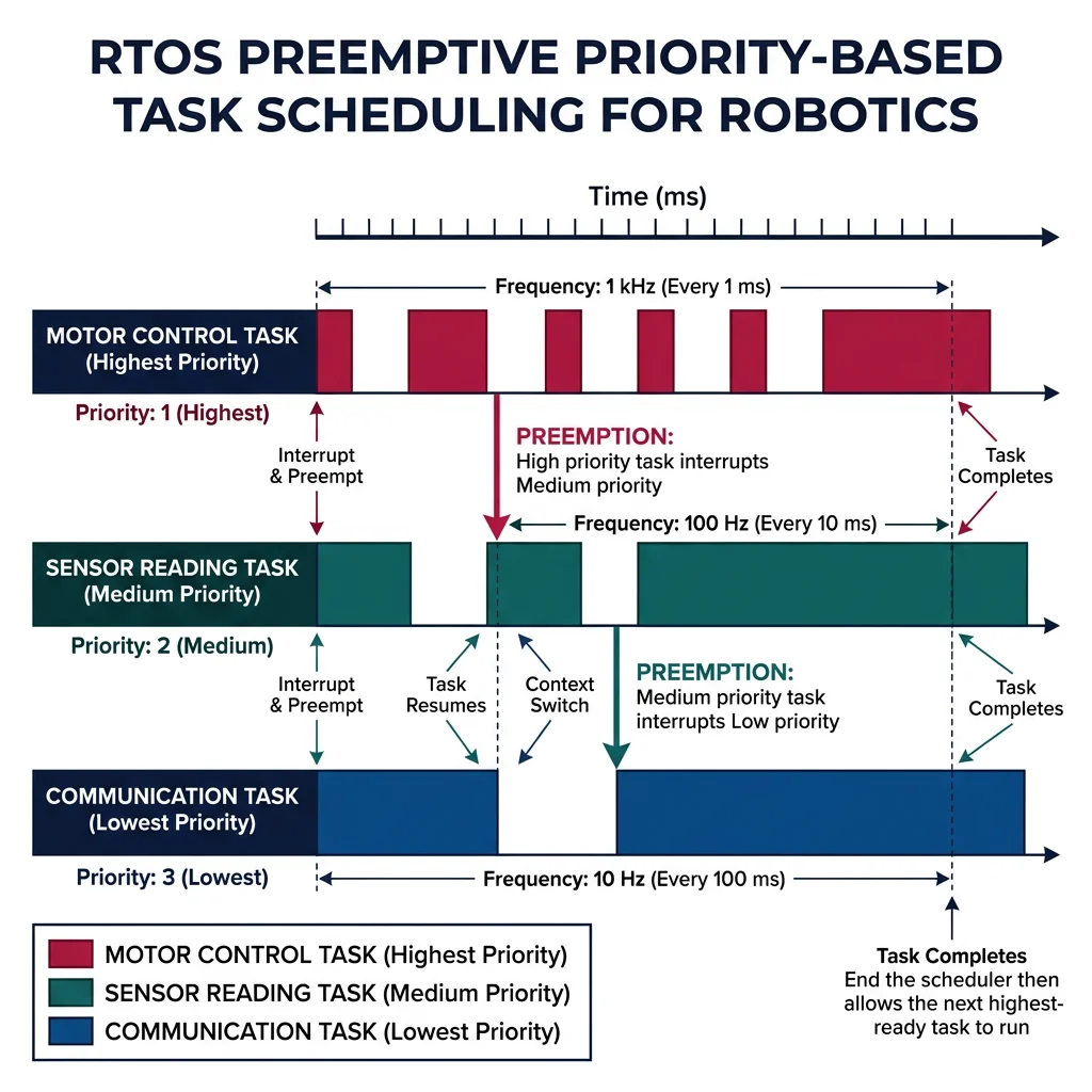
Real-Time Operating Systems & Interrupts
A Real-Time Operating System (RTOS) allows multiple tasks to share one processor with guaranteed timing. Instead of one big loop(), you create separate tasks for control, communication, and sensing — each with its own priority and deadline.
| RTOS | License | Best For | Key Feature |
|---|---|---|---|
| FreeRTOS | MIT | General embedded, AWS IoT | Most popular, huge community, AWS integration |
| Zephyr | Apache 2.0 | IoT, wearables, BLE | Linux Foundation backed, excellent hardware support |
| ChibiOS | GPL/Commercial | STM32 robotics | Tight STM32 integration, HAL included |
| RT-Thread | Apache 2.0 | Chinese MCU ecosystem | Rich middleware, package manager |
| NuttX | Apache 2.0 | Drones (PX4 Autopilot) | POSIX compliance, used in PX4/ArduPilot |
// FreeRTOS: Multi-task robot controller
// Task 1: Motor control at 1 kHz (highest priority)
// Task 2: Sensor reading at 100 Hz (medium priority)
// Task 3: Communication at 10 Hz (lowest priority)

#include "FreeRTOS.h"
#include "task.h"
#include "semphr.h"

SemaphoreHandle_t dataMutex;
volatile float sensor_data = 0;
volatile float motor_command = 0;

// High-priority task: Motor control loop (1 kHz)
void vMotorControlTask(void *pvParameters) {
    TickType_t xLastWakeTime = xTaskGetTickCount();

    while (1) {
        // Read shared sensor data safely
        xSemaphoreTake(dataMutex, portMAX_DELAY);
        float reading = sensor_data;
        xSemaphoreGive(dataMutex);

        // PID control computation
        float error = 100.0f - reading;
        motor_command = 2.0f * error;  // simplified P control

        // Write to motor hardware
        set_motor_pwm((int)motor_command);

        // Sleep until next period (1 ms = 1 kHz)
        vTaskDelayUntil(&xLastWakeTime, pdMS_TO_TICKS(1));
    }
}

// Medium-priority task: Sensor reading (100 Hz)
void vSensorTask(void *pvParameters) {
    TickType_t xLastWakeTime = xTaskGetTickCount();

    while (1) {
        float raw = read_adc_sensor();
        float filtered = apply_low_pass_filter(raw);

        // Update shared data safely
        xSemaphoreTake(dataMutex, portMAX_DELAY);
        sensor_data = filtered;
        xSemaphoreGive(dataMutex);

        vTaskDelayUntil(&xLastWakeTime, pdMS_TO_TICKS(10));  // 10 ms = 100 Hz
    }
}

// Low-priority task: Communication (10 Hz)
void vCommTask(void *pvParameters) {
    TickType_t xLastWakeTime = xTaskGetTickCount();

    while (1) {
        // Send telemetry over UART
        printf("Sensor: %.2f  Motor: %.2f\r\n", sensor_data, motor_command);

        vTaskDelayUntil(&xLastWakeTime, pdMS_TO_TICKS(100));  // 100 ms = 10 Hz
    }
}

int main(void) {
    hardware_init();
    dataMutex = xSemaphoreCreateMutex();

    // Create tasks with priorities (higher number = higher priority)
    xTaskCreate(vMotorControlTask, "Motor", 256, NULL, 3, NULL);
    xTaskCreate(vSensorTask, "Sensor", 256, NULL, 2, NULL);
    xTaskCreate(vCommTask, "Comm", 256, NULL, 1, NULL);

    vTaskStartScheduler();  // Start RTOS — never returns
    while (1) {}
}
Interrupt Handling
Interrupts are the most critical concept in embedded systems. An interrupt pauses the current code, runs a short handler function (ISR — Interrupt Service Routine), then resumes. This ensures time-critical events (encoder pulses, safety signals) are never missed.
- Keep them short — set a flag, increment a counter, read a register. Never do complex math or I/O in an ISR.
- No blocking calls — no
delay(), noSerial.print(), no mutex waits. - Use
volatile— any variable shared between ISR and main code must be declaredvolatile. - Disable/enable carefully — use atomic operations or critical sections when reading multi-byte shared data.
PWM Control
Pulse Width Modulation (PWM) controls motor speed and servo position by rapidly switching a digital pin on and off. The duty cycle (percentage of time the signal is HIGH) determines the average voltage delivered to the motor.
- 0% duty = motor stopped
- 50% duty = half speed (on a 12V supply, motor sees ~6V average)
- 100% duty = full speed
PWM frequency matters: too low (<1 kHz) causes audible whining; too high (>20 kHz) may exceed driver switching speed. Standard motor PWM: 20 kHz. Servo PWM: 50 Hz with 1-2ms pulse width.
// STM32: Hardware PWM for motor and servo control
// Timer 1: Motor PWM at 20 kHz
// Timer 2: Servo PWM at 50 Hz

#include "stm32f4xx_hal.h"

// Configure Timer 1 for 20 kHz motor PWM
// Clock = 168 MHz, Prescaler = 0, Period = 8399
// PWM freq = 168MHz / (0+1) / (8399+1) = 20 kHz
void motor_pwm_init(void) {
    TIM_OC_InitTypeDef sConfigOC = {0};
    sConfigOC.OCMode = TIM_OCMODE_PWM1;
    sConfigOC.Pulse = 0;        // start at 0% duty
    sConfigOC.OCPolarity = TIM_OCPOLARITY_HIGH;
    HAL_TIM_PWM_ConfigChannel(&htim1, &sConfigOC, TIM_CHANNEL_1);
    HAL_TIM_PWM_Start(&htim1, TIM_CHANNEL_1);
}

// Set motor speed: 0-100%
void set_motor_speed(float percent) {
    uint16_t pulse = (uint16_t)(percent / 100.0f * 8399);
    __HAL_TIM_SET_COMPARE(&htim1, TIM_CHANNEL_1, pulse);
}

// Set servo angle: 0-180 degrees
// Servo expects 1ms (0°) to 2ms (180°) pulse at 50 Hz
// Timer period = 20000 (for 1us resolution at 50Hz)
void set_servo_angle(float degrees) {
    float pulse_ms = 1.0f + (degrees / 180.0f);  // 1ms to 2ms
    uint16_t pulse = (uint16_t)(pulse_ms * 1000);  // convert to timer ticks
    __HAL_TIM_SET_COMPARE(&htim2, TIM_CHANNEL_1, pulse);
}
Serial Communication Protocols
Robots are distributed systems — sensors, motor drivers, and processors must exchange data reliably. Choosing the right communication protocol is critical for performance and reliability.
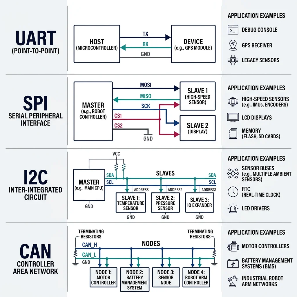
UART (Universal Asynchronous Receiver-Transmitter)
UART is the simplest serial protocol: two wires (TX and RX), no clock signal — both devices must agree on baud rate beforehand. Common baud rates: 9600, 115200, 921600.
| Protocol | Wires | Max Speed | Topology | Max Distance | Robotics Use |
|---|---|---|---|---|---|
| UART | 2 (TX, RX) | ~1 Mbps | Point-to-point | ~15m | GPS, Bluetooth, debug console |
| SPI | 4 (MOSI, MISO, SCK, CS) | ~50 Mbps | Master-slave | ~1m | IMU, flash memory, display |
| I2C | 2 (SDA, SCL) | ~3.4 Mbps | Multi-master bus | ~1m | Sensor arrays, EEPROM, RTC |
| CAN | 2 (CAN_H, CAN_L) | 1 Mbps | Multi-master bus | ~40m (1Mbps) | Automotive, industrial, multi-joint |
SPI & I2C
SPI (Serial Peripheral Interface) is the fastest short-range protocol. Uses a clock signal (SCK) so there's no baud rate agreement needed. The master sends data on MOSI and receives on MISO. Each slave needs a separate chip-select (CS) line, which limits scalability but ensures speed.
I2C (Inter-Integrated Circuit) uses just two wires for multiple devices on one bus. Each device has a unique 7-bit address (0x00-0x7F). Slower than SPI but more scalable — ideal for connecting 10+ sensors on the same two wires.
// I2C: Reading MPU6050 IMU (accelerometer + gyroscope)
// I2C address: 0x68

#include "stm32f4xx_hal.h"

#define MPU6050_ADDR  (0x68 << 1)  // HAL expects left-shifted address
#define PWR_MGMT_1    0x6B
#define ACCEL_XOUT_H  0x3B

typedef struct {
    float ax, ay, az;   // accelerometer (g)
    float gx, gy, gz;   // gyroscope (deg/s)
} IMU_Data;

HAL_StatusTypeDef mpu6050_init(I2C_HandleTypeDef *hi2c) {
    uint8_t data = 0x00;  // wake up (clear sleep bit)
    return HAL_I2C_Mem_Write(hi2c, MPU6050_ADDR, PWR_MGMT_1, 1, &data, 1, 100);
}

IMU_Data mpu6050_read(I2C_HandleTypeDef *hi2c) {
    uint8_t buf[14];
    IMU_Data imu = {0};

    // Read 14 bytes starting from ACCEL_XOUT_H (accel + temp + gyro)
    if (HAL_I2C_Mem_Read(hi2c, MPU6050_ADDR, ACCEL_XOUT_H, 1, buf, 14, 100) == HAL_OK) {
        // Combine high and low bytes, convert to physical units
        imu.ax = (int16_t)(buf[0] << 8 | buf[1]) / 16384.0f;   // ±2g range
        imu.ay = (int16_t)(buf[2] << 8 | buf[3]) / 16384.0f;
        imu.az = (int16_t)(buf[4] << 8 | buf[5]) / 16384.0f;
        // buf[6-7] = temperature (skip)
        imu.gx = (int16_t)(buf[8] << 8 | buf[9]) / 131.0f;     // ±250°/s range
        imu.gy = (int16_t)(buf[10] << 8 | buf[11]) / 131.0f;
        imu.gz = (int16_t)(buf[12] << 8 | buf[13]) / 131.0f;
    }
    return imu;
}
CAN Bus
CAN (Controller Area Network) is the dominant protocol in automotive and industrial robotics. Originally designed by Bosch for cars, CAN is robust, multi-master, and fault-tolerant — messages are broadcast to all nodes, with hardware arbitration ensuring the highest-priority message always wins.
Case Study: DYNAMIXEL Servo System
ROBOTIS DYNAMIXEL servos are used in research robots worldwide (TurtleBot, DARWIN-OP humanoid). Each servo is a complete system with motor, encoder, controller, and communication — daisy-chained on a single half-duplex UART bus:
- Protocol: Custom packet format over half-duplex UART at 1-4.5 Mbps
- Addressing: Each servo has a unique ID (0-253), supporting up to 254 on one bus
- Features: Position, velocity, current control, temperature monitoring, hardware PID, sync read/write for coordinated motion
- Sync Write: One command updates all 6 servos simultaneously — critical for coordinated joint trajectories
Advanced Embedded Topics
Power Management
Power management is often the most overlooked aspect of embedded robotics — and the most common cause of mysterious failures. Motors create voltage spikes, batteries have varying voltage, and MCUs need stable power.
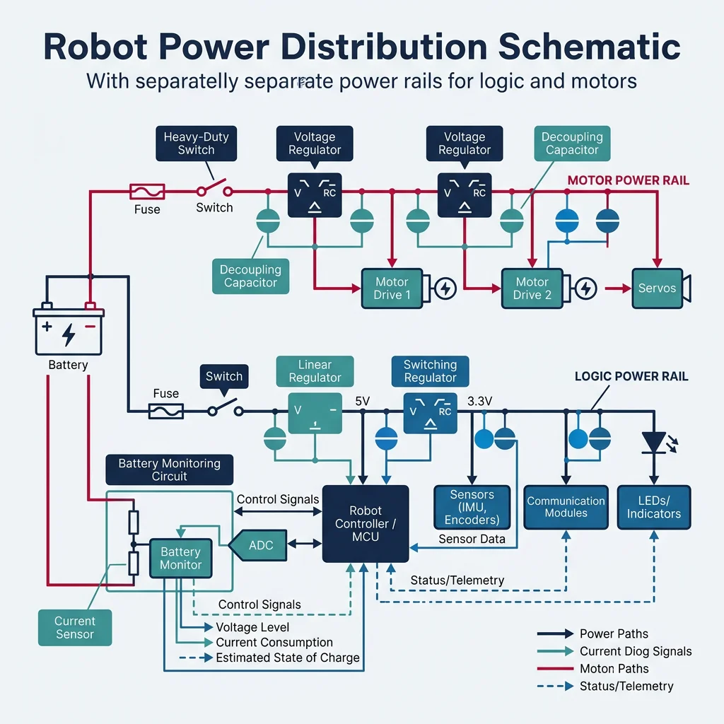
- Separate power rails: Never power motors and logic from the same regulator. Motor current surges cause logic brownouts.
- Decoupling capacitors: 100nF ceramic capacitors on every IC power pin, plus 10-100µF bulk capacitors near motor drivers.
- Battery monitoring: Use ADC to measure battery voltage through a resistor divider. Implement low-voltage cutoff to prevent damage.
- Sleep modes: STM32 offers Stop, Standby, and Shutdown modes — drawing as little as 1.8µA for battery-powered field robots.
Embedded Safety Systems
A robot that loses control can injure people or damage equipment. Embedded safety mechanisms include:
- Watchdog Timer (WDT): Hardware timer that resets the MCU if software hangs — the program must periodically "kick" the watchdog to prove it's alive
- Emergency Stop (E-Stop): Hardware interrupt connected to a physical button that immediately disables all motor outputs via relay or contactor — never software-only
- Current monitoring: Measure motor current with shunt resistors + ADC. If current exceeds limits, disable the motor driver within microseconds
- Redundant communication: Critical systems use dual CAN buses — if one fails, the other takes over
FPGA Basics
An FPGA (Field-Programmable Gate Array) is not a processor — it's reconfigurable hardware. You design digital circuits (in VHDL/Verilog), and the FPGA physically wires itself to implement your design. This means truly parallel, deterministic processing at hardware speed.
| Feature | MCU | FPGA |
|---|---|---|
| Processing | Sequential (one instruction at a time) | Massively parallel (thousands of operations simultaneously) |
| Latency | Microseconds (instruction pipeline) | Nanoseconds (direct hardware path) |
| Programming | C/C++ (software) | VHDL/Verilog (hardware description) |
| Best for | General-purpose control, algorithms | High-speed I/O, parallel sensor processing, custom protocols |
| Robotics use | Main controller, communication | LiDAR processing, motor drive timing, real-time vision |
Edge Computing for Robotics
Edge computing brings AI processing directly onto the robot, avoiding cloud latency. Dedicated AI accelerators can run neural networks for object detection, speech recognition, and path planning locally.
| Platform | Performance | Power | Use Case |
|---|---|---|---|
| NVIDIA Jetson Nano | 472 GFLOPS | 5-10W | Entry-level vision, hobby robots |
| NVIDIA Jetson Orin NX | 100 TOPS | 10-25W | Advanced autonomy, multi-camera systems |
| Google Coral TPU | 4 TOPS | 2W | Low-power inference, smart cameras |
| Intel Neural Compute Stick | 4 TOPS | 1W (USB) | Add AI to existing embedded systems |
| Raspberry Pi 5 | CPU only | 4-12W | High-level processing, ROS node |
Case Study: PX4 Autopilot Architecture
The PX4 Autopilot (used in commercial drones from 3DR, Holybro, and others) is an exemplary embedded robotics architecture:
- MCU: STM32F765 (Cortex-M7 at 216 MHz) or STM32H753 (480 MHz) on Pixhawk hardware
- RTOS: NuttX — POSIX-compliant, providing threads, timers, and file system abstraction
- Sensors: Dual IMUs (SPI at 8 MHz), barometer (I2C), magnetometer (I2C), GPS (UART at 115200 baud)
- Communication: MAVLink protocol over UART/UDP, CAN for ESC control, PWM for servos
- Safety: Dual redundant IMUs, watchdog timer, hardware arming switch, geofencing, return-to-launch failsafe
- Companion computer: Jetson or Raspberry Pi for vision and AI, connected via UART/Ethernet
Embedded System Spec Sheet
Document your robot's embedded architecture. Enter the hardware and software configuration and download a professional specification sheet.
Embedded System Spec Sheet
Document your MCU, communication protocols, and peripherals. Download as Word, Excel, or PDF.
All data stays in your browser. Nothing is sent to or stored on any server.
Exercises & Challenges
Exercise 1: Multi-Sensor I2C Bus
Connect an MPU6050 (address 0x68), BMP280 barometer (0x76), and HMC5883L magnetometer (0x1E) on the same I2C bus. Write a program that reads all three sensors at different rates (IMU: 100 Hz, barometer: 10 Hz, magnetometer: 50 Hz) and prints formatted data to serial.
Exercise 2: FreeRTOS Robot Controller
Implement a FreeRTOS application with three tasks: (1) Motor PID at 1 kHz, (2) Ultrasonic sensor at 20 Hz, (3) LED status indicator at 2 Hz. Use a queue to pass distance measurements from the sensor task to the motor task, which adjusts speed based on distance.
Exercise 3: CAN Bus Multi-Node Network
Design a CAN bus network with 3 nodes: (1) Master controller sending position commands, (2) Left motor driver reporting encoder counts, (3) Right motor driver reporting encoder counts. Define message IDs, implement transmit/receive, and handle bus errors gracefully.
Conclusion & Next Steps
Embedded systems are where robotics theory becomes physical reality. We've covered the essential hardware and software layers:
- Microcontrollers: Arduino for prototyping, STM32 for production — each with distinct strengths
- RTOS: FreeRTOS and others enable multi-tasking with guaranteed timing for real-time control
- Communication: UART, SPI, I2C, and CAN each serve specific roles in the robot's nervous system
- PWM & Interrupts: The fundamental mechanisms for motor control and responsive sensor reading
- Edge computing: NVIDIA Jetson and similar platforms bring AI directly onto the robot