We use cookies to enhance your browsing experience, serve personalized content, and analyze our traffic.
By clicking "Accept All", you consent to our use of cookies. See our
Privacy Policy
for more information.
Kernel Development Series Phase 1: How a Computer Starts
February 6, 2026Wasil Zafar25 min read
Understand how a computer boots from power-on to kernel execution. Learn about CPU reset state, BIOS vs UEFI boot processes, and set up your complete OS development environment with cross-compilers and emulators.
Phase 1 Goals: By the end of this phase, you'll understand exactly what happens from the moment you press the power button until your kernel starts executing. You'll also have a working development environment ready to build your own OS.
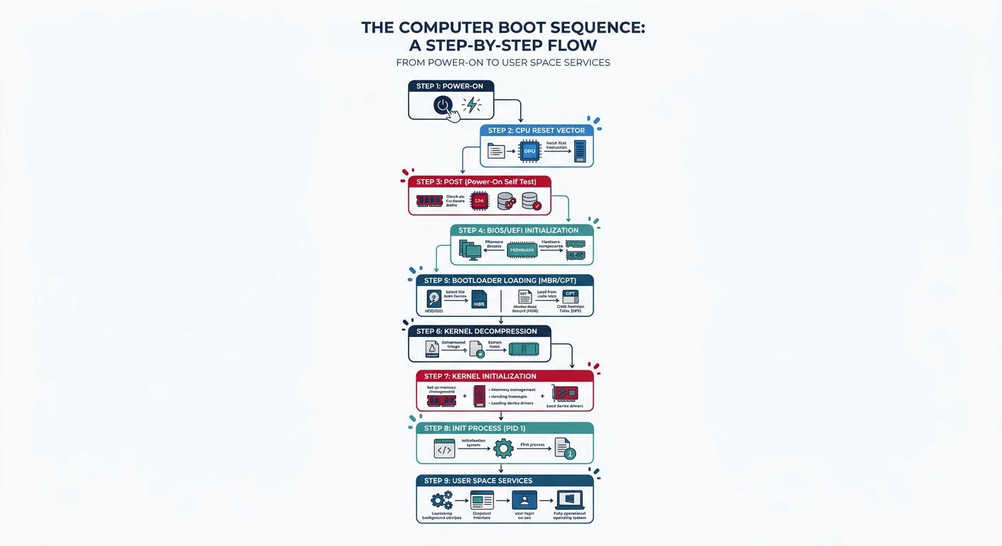
You press the power button. A few seconds later, you see a login screen or hear the familiar startup chime. But what actually happens in those crucial seconds? This phase reveals the mystery of the boot process - a carefully orchestrated sequence that transforms dead silicon into a running operating system.
The boot journey: from pressing the power button through firmware initialization, bootloader execution, and finally kernel startup
Think of booting a computer like waking up in the morning. When you wake up, you don't immediately start solving complex problems. Instead:
The Wake-Up Analogy
Physical startup - Eyes open, body initializes (= power on, CPU starts)
Basic check - Am I in my bed? Body feels okay? (= POST self-test)
Load knowledge - Remember who you are, what you do (= load operating system)
Start work - Go to your job and be productive (= run applications)
Key Insight: The boot process is deterministic and predictable. Every x86 computer follows the same fundamental sequence from power-on to kernel execution. Once you understand this sequence, you control the machine from its very first instruction.
Here's what happens in the first seconds after you press power:
TIME        EVENT                               DURATION
═════════════════════════════════════════════════════════════════
0.000s      Power button pressed                 -
0.001s      PSU sends "Power Good" signal       ~100ms
0.100s      CPU reset vector executed            -
0.101s      BIOS/UEFI firmware runs             2-5s
            - POST (Power-On Self-Test)
            - Hardware initialization
            - Boot device search
3.000s      Bootloader loaded (512 bytes)       <100ms
3.100s      Bootloader runs
            - Displays boot menu (optional)
            - Loads kernel into memory
            - Prepares CPU mode transition
4.000s      Kernel starts executing             ~500ms
            - Initializes core systems
            - Mounts root filesystem
            - Starts init process
5.000s      Init/systemd runs                   2-10s
            - Starts system services
            - Brings up networking
            - Starts display manager
10.000s     Login screen appears                 -
═════════════════════════════════════════════════════════════════
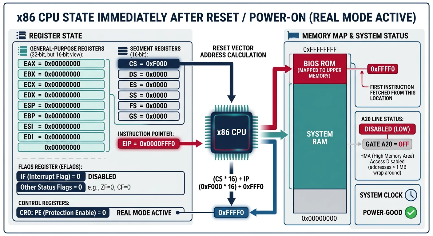
CPU Reset State & First Instruction
When power is applied to an x86 CPU, it enters a predictable reset state. Understanding this state is crucial because this is exactly where our kernel development begins.
x86 CPU state at reset: all registers are initialized to known values, with CS:IP pointing to 0xFFFF0 — the very first instruction
What Happens at Power On
When power stabilizes, the CPU performs a hardware reset:
Real Mode: The CPU always starts in "real mode" - a 16-bit operating mode dating back to the original 8086 (1978). In real mode, you can only access the first 1MB of memory, there's no memory protection, and all code runs at the highest privilege level.
First Instruction Execution
The magic number is 0xFFFFFFF0 - the reset vector. This address is "wired" to point to firmware (BIOS/UEFI) stored on a ROM chip on your motherboard.
The first instruction the CPU executes is typically a far jump:
; This is literally the first instruction executed on x86
; Located at physical address 0xFFFFFFF0
jmp 0xF000:0xE05B    ; Jump to BIOS entry point
; The BIOS begins its initialization routine here
Why 0xFFFFFFF0?
You might wonder: "If the CPU is in 16-bit real mode, how can it access address 0xFFFFFFF0 (a 32-bit address)?"
The answer is a hardware trick. At reset, the CPU sets a hidden "high address bits" flag that points to the top of the 4GB address space. The first far jump clears this flag and drops the CPU into normal real mode addressing within the first 1MB.
This design ensures backward compatibility with the original PC while allowing modern firmware to be larger and more sophisticated.
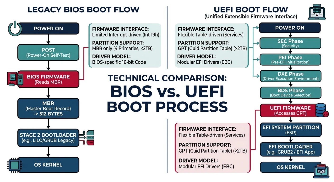
BIOS vs UEFI Boot Process
There are two firmware standards for booting x86 computers. Understanding both is essential because your OS may need to support either.
BIOS vs UEFI boot flow: legacy BIOS uses a simple 512-byte MBR, while UEFI provides a richer firmware environment with GPT partition support
BIOS (Basic Input/Output System) dates back to the original IBM PC in 1981. Despite its age, it's still widely used and is simpler to develop for.
LEGACY BIOS BOOT SEQUENCE
═══════════════════════════════════════════════════════════════

1. POWER-ON SELF-TEST (POST)
   ├─→ Test CPU
   ├─→ Test first 64KB RAM
   ├─→ Initialize chipset
   ├─→ Detect video card, initialize display
   └─→ Beep codes indicate errors

2. HARDWARE DETECTION
   ├─→ Enumerate PCI devices
   ├─→ Detect drives (IDE, SATA)
   ├─→ Initialize USB controllers
   └─→ Build equipment list in BIOS Data Area

3. BOOT DEVICE SEARCH
   ├─→ Check boot order (CMOS settings)
   ├─→ For each device in order:
   │   ├─→ Read first sector (512 bytes)
   │   ├─→ Check for boot signature (0xAA55 at offset 510)
   │   └─→ If found: load to 0x7C00 and execute
   └─→ If no bootable device: display error

4. BOOTLOADER EXECUTION
   └─→ CPU begins executing at 0x0000:0x7C00
       (Your code runs here!)
═══════════════════════════════════════════════════════════════
The Magic Number 0x7C00: Why this specific address? IBM engineers chose it in 1981 to leave room for the interrupt vector table (0-0x400) and BIOS data area (0x400-0x500), while providing about 30KB of space before the boot sector for stack and data.
BIOS Interrupts: BIOS provides services via software interrupts. Your bootloader can call these:
; Example: Print character using BIOS interrupt
mov ah, 0x0E        ; BIOS teletype function
mov al, 'H'         ; Character to print
int 0x10            ; Call BIOS video interrupt

; Example: Read sector from disk
mov ah, 0x02        ; BIOS read sectors function
mov al, 1           ; Number of sectors to read
mov ch, 0           ; Cylinder number
mov cl, 2           ; Sector number (starts at 1)
mov dh, 0           ; Head number
mov dl, 0x80        ; Drive number (0x80 = first hard disk)
mov bx, 0x1000      ; Destination: ES:BX
int 0x13            ; Call BIOS disk interrupt
Modern UEFI Boot Process
UEFI (Unified Extensible Firmware Interface) is the modern replacement for BIOS, developed primarily by Intel starting in the late 1990s.
UEFI BOOT SEQUENCE
═══════════════════════════════════════════════════════════════

1. SEC (Security Phase)
   └─→ Minimal code, verifies integrity of firmware

2. PEI (Pre-EFI Initialization)
   ├─→ Initialize CPU
   ├─→ Initialize memory controller
   ├─→ Discover and initialize chipset
   └─→ Create HOBs (Hand-Off Blocks) for DXE

3. DXE (Driver Execution Environment)
   ├─→ Load and execute EFI drivers
   ├─→ Initialize all hardware
   ├─→ Build system tables (ACPI, SMBIOS)
   └─→ Establish UEFI services (boot/runtime)

4. BDS (Boot Device Selection)
   ├─→ Load EFI boot manager
   ├─→ Process boot options
   ├─→ Find EFI System Partition (ESP)
   │   └─→ Usually /EFI/BOOT/BOOTX64.EFI
   └─→ Load and execute EFI application (bootloader/kernel)

5. TSL (Transient System Load)
   └─→ Call ExitBootServices()
       └─→ UEFI hands control to OS, becomes runtime-only
═══════════════════════════════════════════════════════════════
EFI System Partition (ESP)
UEFI uses a dedicated FAT32 partition to store bootloaders:
Our Approach: We'll start with BIOS boot (Phases 2-10) because it's simpler and teaches fundamental concepts. In Phase 12, we'll implement UEFI boot for modern systems. Many real-world bootloaders (like GRUB) support both.
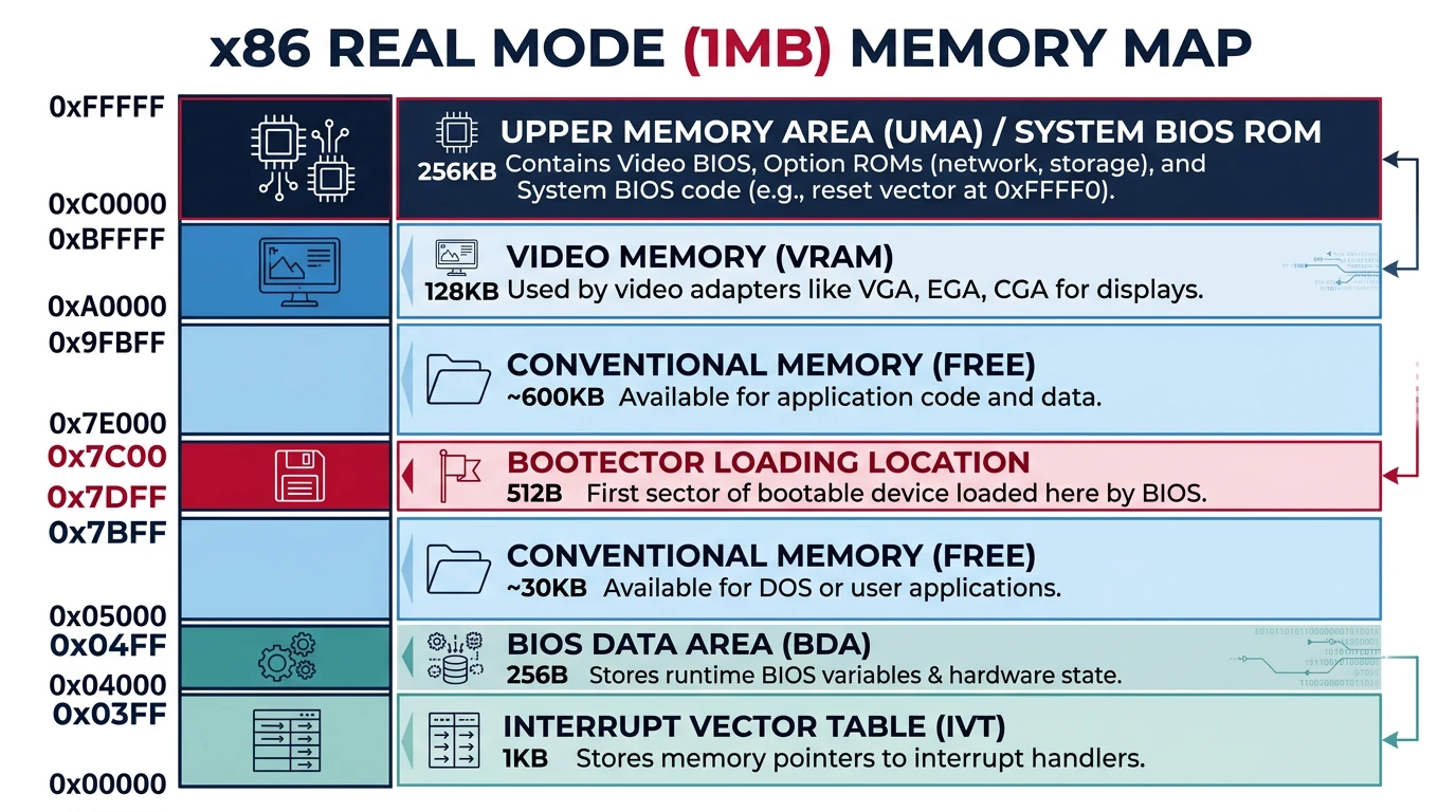
Early Memory Layout
Memory Map at Boot Time
When BIOS loads your bootloader, memory is in a specific state. Understanding this layout is critical for writing working boot code:
Real mode memory map: the first 1MB is divided into IVT, BDA, free conventional memory, video memory, and ROM BIOS regions
REAL MODE MEMORY MAP (First 1MB)
═══════════════════════════════════════════════════════════════

        ┌────────────────────────────────────────┐
0x100000│ Extended Memory (requires mode switch) │← We'll use this later
        ├────────────────────────────────────────┤
0x0FFFFF│                                        │
        │    HIGH MEMORY AREA (HMA)              │
        │    (accessible with A20 gate enabled)  │
0x0FFFF0├────────────────────────────────────────┤
        │                                        │
        │    BIOS ROM Shadow (usually)           │
        │                                        │
0x0F0000├────────────────────────────────────────┤
        │                                        │
        │    Device ROMs (Video BIOS, etc.)      │
        │                                        │
0x0C8000├────────────────────────────────────────┤
        │    Video BIOS                          │
0x0C0000├────────────────────────────────────────┤
        │                                        │
        │    VIDEO MEMORY                        │
        │    B8000-BFFFF: Text mode              │← Write here to display text!
        │    A0000-AFFFF: Graphics mode          │
        │                                        │
0x0A0000├────────────────────────────────────────┤
        │                                        │
        │                                        │
        │    FREE CONVENTIONAL MEMORY            │
        │    (Approximately 638KB)               │← Load kernel here
        │                                        │
        │                                        │
0x007E00├────────────────────────────────────────┤
        │    YOUR BOOT SECTOR (512 bytes)        │← BIOS loads you here
0x007C00├────────────────────────────────────────┤
        │    Usually free for stack              │
0x000500├────────────────────────────────────────┤
        │    BIOS Data Area (256 bytes)          │← System info, do not overwrite!
0x000400├────────────────────────────────────────┤
        │    Interrupt Vector Table (1KB)        │← 256 interrupt handlers
0x000000└────────────────────────────────────────┘

═══════════════════════════════════════════════════════════════
Hardware Initialization by BIOS
Before your code runs, BIOS has already initialized essential hardware:
Already Initialized
CPU and basic chipset
RAM (memory controller configured)
Interrupt controller (8259 PIC)
Keyboard controller (8042)
Basic video (VGA text mode)
Timer (8253/8254 PIT)
Real-time clock (RTC)
Your Responsibility
Enable A20 line (for >1MB access)
Set up GDT (for protected mode)
Switch CPU modes
Initialize your own IDT
Set up paging
Initialize additional devices
Kernel Loading Sequence
A typical boot sequence for a BIOS-based bootloader:
; TYPICAL BIOS BOOT SEQUENCE
; ══════════════════════════════════════════════════════════════

; Stage 1: Boot Sector (first 512 bytes)
; ────────────────────────────────────────
boot_sector_start:
    ; 1. Set up segments and stack
    xor ax, ax
    mov ds, ax
    mov es, ax
    mov ss, ax
    mov sp, 0x7C00      ; Stack grows down from boot sector

    ; 2. Display loading message
    mov si, msg_loading
    call print_string

    ; 3. Load more sectors from disk (Stage 2)
    mov ah, 0x02        ; BIOS read sectors
    mov al, 10          ; Read 10 sectors
    mov ch, 0           ; Cylinder 0
    mov cl, 2           ; Start from sector 2
    mov dh, 0           ; Head 0
    mov bx, 0x1000      ; Load to 0x0000:0x1000
    int 0x13
    jc disk_error

    ; 4. Jump to Stage 2
    jmp 0x0000:0x1000

; Stage 2: Extended Bootloader
; ────────────────────────────────────────
stage2_start:
    ; 5. Enable A20 line
    call enable_a20

    ; 6. Load GDT
    lgdt [gdt_descriptor]

    ; 7. Switch to Protected Mode
    mov eax, cr0
    or eax, 1
    mov cr0, eax

    ; 8. Far jump to 32-bit code
    jmp 0x08:protected_mode_start

[BITS 32]
protected_mode_start:
    ; 9. Set up 32-bit segments
    mov ax, 0x10
    mov ds, ax
    mov es, ax
    mov ss, ax
    mov esp, 0x90000    ; New stack in extended memory

    ; 10. Load kernel from disk (using our own driver now)
    call load_kernel

    ; 11. Jump to kernel entry point
    jmp KERNEL_ENTRY_POINT
We'll Implement This: Don't worry if this looks complex. In Phase 2 and 3, we'll write this code step by step, explaining every instruction. You'll understand exactly why each line is necessary.
Setting Up Your Development Environment
Before writing any OS code, you need the right tools. Operating system development has three special requirements:
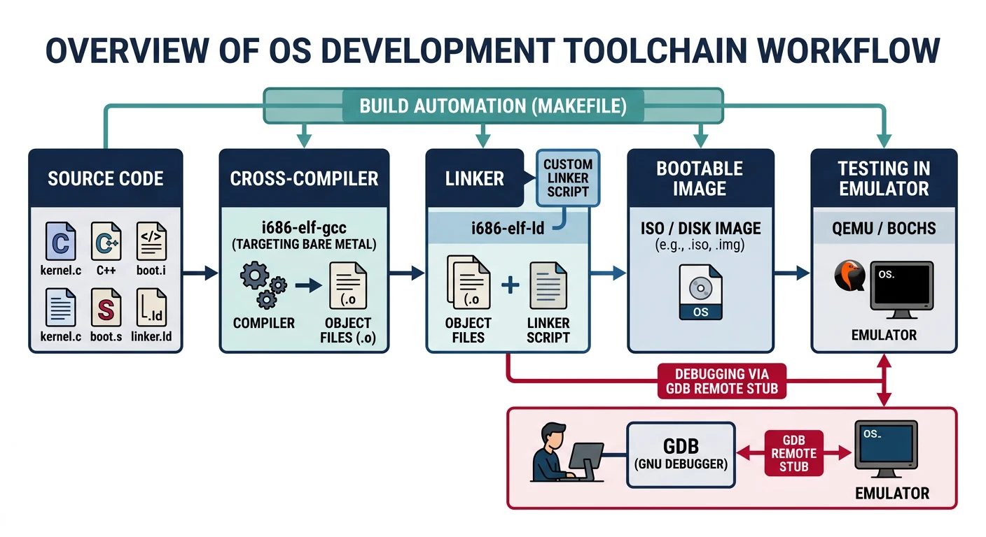
OS development toolchain: a cross-compiler targets bare metal, an emulator (QEMU) tests without rebooting, and GDB provides instruction-level debugging
Cross-compiler - A compiler that generates code for a different target
Emulator - Run your OS without rebooting real hardware
Debugger - Step through code instruction by instruction
Cross-Compilers: Building for Bare Metal
Your normal compiler (like gcc on Linux) produces executables for your host OS. But your kernel IS the OS - it can't depend on Linux libraries or system calls. You need a cross-compiler that targets "bare metal" x86.
Why Not Use System GCC? Your system's GCC is configured to link against libc, use your OS's calling conventions, and may add extra code (like stack protectors) that won't work without an OS. A cross-compiler avoids all these problems.
Building a GCC Cross-Compiler:
# Prerequisites (Ubuntu/Debian)
sudo apt update
sudo apt install build-essential bison flex libgmp3-dev libmpc-dev \
                 libmpfr-dev texinfo wget

# Create working directory
export PREFIX="$HOME/opt/cross"
export TARGET=i686-elf
export PATH="$PREFIX/bin:$PATH"
mkdir -p $HOME/src && cd $HOME/src

# Download sources
wget https://ftp.gnu.org/gnu/binutils/binutils-2.41.tar.xz
wget https://ftp.gnu.org/gnu/gcc/gcc-13.2.0/gcc-13.2.0.tar.xz
tar xf binutils-2.41.tar.xz
tar xf gcc-13.2.0.tar.xz

# Build Binutils
mkdir build-binutils && cd build-binutils
../binutils-2.41/configure --target=$TARGET --prefix="$PREFIX" \
    --with-sysroot --disable-nls --disable-werror
make -j$(nproc)
make install
cd ..

# Build GCC
mkdir build-gcc && cd build-gcc
../gcc-13.2.0/configure --target=$TARGET --prefix="$PREFIX" \
    --disable-nls --enable-languages=c,c++ --without-headers
make -j$(nproc) all-gcc all-target-libgcc
make install-gcc install-target-libgcc
cd ..

# Verify installation
i686-elf-gcc --version
# Should output: i686-elf-gcc (GCC) 13.2.0
Windows Users: WSL2 Recommended
The easiest way to develop on Windows is using WSL2 (Windows Subsystem for Linux):
# Install WSL2 with Ubuntu (PowerShell as Admin)
wsl --install -d Ubuntu

# After restart, open Ubuntu and follow Linux instructions above
Alternatively, use a pre-built cross-compiler from the OSDev Wiki.
Emulators (QEMU, Bochs)
Testing an OS on real hardware requires rebooting, which takes time and risks corrupting your development machine. Emulators solve this by running a virtual PC inside your operating system.
QEMU (Recommended)
Pros: Fast, accurate, great GDB integration, supports many architectures
Cons: Errors can be cryptic
# Install on Ubuntu/Debian
sudo apt install qemu-system-x86

# Run your OS image
qemu-system-i386 -fda myos.img

# With debugging enabled
qemu-system-i386 -fda myos.img \
    -s -S    # -s = GDB on port 1234
             # -S = freeze at startup
Bochs
Pros: Built-in debugger, very detailed logging, catches subtle bugs
Cons: Slower than QEMU
# Install on Ubuntu/Debian
sudo apt install bochs bochs-x

# Bochs requires a config file (bochsrc.txt)
# Example config:
megs: 32
romimage: file=/usr/share/bochs/BIOS-bochs-latest
vgaromimage: file=/usr/share/bochs/VGABIOS-lgpl-latest
floppya: 1_44=myos.img, status=inserted
boot: floppy
Debuggers (GDB)
When your kernel triple-faults and the screen goes blank, you need a debugger. GDB can connect to QEMU and let you step through your kernel instruction by instruction.
# Terminal 1: Start QEMU with debugging
qemu-system-i386 -fda myos.img -s -S

# Terminal 2: Connect GDB
gdb
(gdb) target remote localhost:1234
(gdb) symbol-file kernel.elf          # Load debug symbols
(gdb) break kmain                      # Set breakpoint at kernel entry
(gdb) continue                         # Start execution
(gdb) layout asm                       # Show assembly view
(gdb) stepi                            # Step one instruction
(gdb) info registers                   # View all registers
(gdb) x/20x 0x7C00                    # Examine memory
Essential GDB Commands for OS Development:
target remote localhost:1234 - Connect to QEMU
set architecture i386 - Tell GDB we're in 32-bit mode
stepi / nexti - Step one instruction
x/10i $eip - Disassemble next 10 instructions
info registers - Show all register values
watch *0xB8000 - Break when video memory changes
Complete Environment Installation Script
Here's a script that sets up everything on Ubuntu/Debian:
#!/bin/bash
# setup-osdev.sh - Complete OS Development Environment Setup

set -e  # Exit on error

echo "=== Installing OS Development Tools ==="

# Install packages
sudo apt update
sudo apt install -y \
    build-essential \
    nasm \
    qemu-system-x86 \
    gdb \
    xorriso \
    mtools \
    grub-pc-bin \
    grub-common

# Create project structure
mkdir -p ~/osdev/{src,build,iso}
cd ~/osdev

# Create a simple Makefile template
cat > Makefile << 'EOF'
ASM=nasm
CC=i686-elf-gcc
LD=i686-elf-ld

ASMFLAGS=-f elf32
CFLAGS=-ffreestanding -nostdlib -nostdinc -fno-builtin -fno-stack-protector -m32

all: myos.img

boot.o: src/boot.asm
	$(ASM) -f bin src/boot.asm -o build/boot.bin

kernel.o: src/kernel.c
	$(CC) $(CFLAGS) -c src/kernel.c -o build/kernel.o

myos.img: boot.o kernel.o
	# Create simple bootable image
	cat build/boot.bin build/kernel.o > build/myos.img
	# Pad to floppy size
	truncate -s 1440K build/myos.img

run: myos.img
	qemu-system-i386 -fda build/myos.img

debug: myos.img
	qemu-system-i386 -fda build/myos.img -s -S &
	gdb -ex "target remote localhost:1234"

clean:
	rm -rf build/*
EOF

echo "=== Setup Complete ==="
echo "Project directory: ~/osdev"
echo "Next: Build the cross-compiler (see instructions above)"
echo "Then: Run 'make' to build and 'make run' to test"
Exercises & What You Can Build
Hands-On Project
Phase 1 Deliverables
A working OS development environment (cross-compiler + QEMU + GDB)
Understanding of the complete boot flow from power-on to kernel
Knowledge of BIOS vs UEFI differences
Debugging skills for code that runs before an OS exists
Exercise 1: Environment Verification
Verify your setup by creating this test:
; test.asm - Minimal boot sector that displays 'X'
[BITS 16]
[ORG 0x7C00]

start:
    mov ah, 0x0E    ; BIOS teletype
    mov al, 'X'     ; Character to print
    int 0x10        ; Call BIOS

    jmp $           ; Infinite loop

times 510-($-$$) db 0   ; Pad to 510 bytes
dw 0xAA55               ; Boot signature
# Assemble and run
nasm -f bin test.asm -o test.img
qemu-system-i386 -fda test.img
# You should see 'X' in the top-left corner!
Exercise 2: Explore BIOS Data Area
Modify the test to read and display information from the BIOS Data Area:
; Read equipment word from BDA
mov ax, 0x0040      ; BDA segment
mov ds, ax
mov ax, [0x0010]    ; Equipment word at 0040:0010
; Bits 0-1: Number of floppy drives
; Bit 2: Pointing device installed
; Bits 4-5: Initial video mode
; etc.
Challenge: Display the number of floppy drives and video mode from the BDA.
Exercise 3: GDB Practice
Using the test boot sector, practice with GDB:
Set a breakpoint at 0x7C00 and verify execution starts there
Single-step through each instruction
Examine the registers before and after the BIOS interrupt
Look at video memory (0xB8000) to see the 'X' character
(gdb) target remote localhost:1234
(gdb) break *0x7C00
(gdb) continue
(gdb) x/5i $pc          # Show next 5 instructions
(gdb) stepi              # Execute one instruction
(gdb) x/2b 0xB8000      # Look at video memory ('X' = 0x58)
Next Steps
You now understand:
The complete boot sequence from power button to kernel
CPU reset state and where execution begins
BIOS vs UEFI boot processes and their trade-offs
Real mode memory layout and the 0x7C00 convention
How to set up a complete OS development environment
Continue the Series
Phase 0: Orientation & Big Picture
Review the fundamentals of operating systems, kernel architectures, and the complete series learning path.