We use cookies to enhance your browsing experience, serve personalized content, and analyze our traffic.
By clicking "Accept All", you consent to our use of cookies. See our
Privacy Policy
for more information.
Phase 14 Goals: By the end of this phase, your OS will have mouse support for GUI interaction, and high-precision timers for accurate scheduling, animations, and time-sensitive operations.
In Phase 13, we built a complete graphics system with framebuffer drawing, fonts, double buffering, and window management. But a graphical interface isn't truly usable until users can interact with it. In this phase, we add the two critical components that transform a static display into an interactive system: precise input handling (mouse) and high-precision timing.
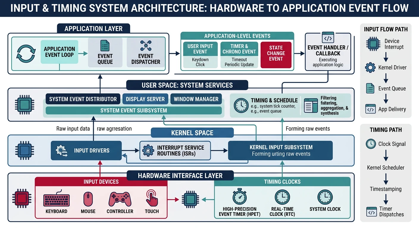
Input and timing architecture — from hardware interrupts to application event handling
Key Insight: A graphical OS needs precise input handling and accurate timing. The mouse makes your GUI interactive, while high-precision timers enable smooth animations, proper scheduling, and accurate time measurement.
System timer (PIT/HPET): Drives the scheduler, maintains system time
APIC timer: Per-CPU timer for multiprocessor scheduling
TSC: Ultra-high resolution for benchmarking (but may not be constant across CPUs)
HPET: Best of both worlds—high resolution and system-wide consistency
PS/2 Mouse Driver
The PS/2 mouse interface dates back to IBM's PS/2 computers (1987), but remains supported on virtually all PCs through USB-to-PS/2 emulation. It's the simplest way to add mouse support to your OS—no USB stack required!
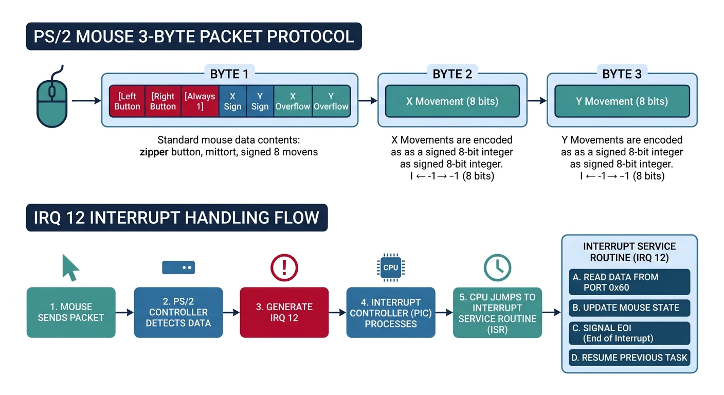
PS/2 mouse protocol — 3-byte packets carrying button state and delta movement via IRQ 12
Mouse Protocol
The PS/2 mouse communicates through the same 8042 keyboard controller we used for keyboard input, but uses a separate data channel (the "auxiliary" port). Think of it like having two phone lines through one switchboard:
╔═════════════════════════════════════════════════════════════════════════════╗║ 8042 KEYBOARD CONTROLLER ║╠═════════════════════════════════════════════════════════════════════════════╣║║║┌────────────────────────┐║║┌──────────┐│ 8042 Controller │┌──────────┐║║│ Keyboard │────────│ Port 0x60: Data │────────│ CPU │║║│ (IRQ 1) ││ Port 0x64: Command ││ │║║└──────────┘│ │└──────────┘║║│ ┌─────────────────┐ │║║┌──────────┐│ │ Status Register │ │║║│ Mouse │────────│ │ Bit 0: Output │ │║║│ (IRQ 12) ││ │ Bit 1: Input │ │║║└──────────┘│ │ Bit 5: Aux data │ │║║│ └─────────────────┘ │║║└────────────────────────┘║║║║Commands to 0x64:Data via 0x60:║║0xA8 = Enable auxiliary (mouse) 0xF4 = Enable data reporting ║║0xA9 = Disable auxiliary 0xF5 = Disable data reporting ║║0xD4 = Write to auxiliary device 0xF6 = Set defaults ║║0x20 = Read controller config 0xFF = Reset mouse ║║║╚═════════════════════════════════════════════════════════════════════════════╝
Before sending data to the mouse or reading from it, we must check the controller's status register:
/* Wait for 8042 controller to be ready */
static void mouse_wait(int type) {
    int timeout = 100000;
    while (timeout--) {
        if (type == 0) {
            // Wait for output buffer full (data ready to read)
            if (inb(0x64) & 0x01) return;
        } else {
            // Wait for input buffer empty (ready to receive command)
            if (!(inb(0x64) & 0x02)) return;
        }
    }
}

/* Write command to mouse */
static void mouse_write(uint8_t data) {
    mouse_wait(1);
    outb(0x64, 0xD4);   // Tell controller: next byte goes to mouse
    mouse_wait(1);
    outb(0x60, data);   // Send the actual command
}

/* Read response from mouse */
static uint8_t mouse_read(void) {
    mouse_wait(0);
    return inb(0x60);
}
The initialization sequence enables the mouse and tells the controller to generate IRQ 12 when mouse data arrives:
/* PS/2 Mouse State */
typedef struct {
    int x, y;               // Current position
    uint8_t buttons;        // Button state
    int8_t  packet[3];      // Current packet
    uint8_t cycle;          // Packet byte index (0-2)
} mouse_t;

mouse_t mouse = {0};

/* Initialize PS/2 mouse */
void mouse_init(void) {
    // Enable auxiliary device (mouse)
    mouse_wait(1);
    outb(0x64, 0xA8);

    // Enable interrupts
    mouse_wait(1);
    outb(0x64, 0x20);
    mouse_wait(0);
    uint8_t status = inb(0x60) | 2;
    mouse_wait(1);
    outb(0x64, 0x60);
    mouse_wait(1);
    outb(0x60, status);

    // Use default settings
    mouse_write(0xF6);
    mouse_read();

    // Enable data reporting
    mouse_write(0xF4);
    mouse_read();
}
Packet Format
PS/2 mice send data in 3-byte packets. Each packet contains button state, X movement, and Y movement. The tricky part is that movement values are signed 9-bit numbers!
╔═════════════════════════════════════════════════════════════════════════════╗║ PS/2 MOUSE PACKET FORMAT (3 bytes) ║╠═════════════════════════════════════════════════════════════════════════════╣║║║BYTE 0 (Status/Buttons):║║┌───┬───┬───┬───┬───┬───┬───┬───┐║║│YOF│XOF│YSN│XSN│ 1 │MID│RGT│LFT│║║└───┴───┴───┴───┴───┴───┴───┴───┘║║7 6 5 4 3 2 1 0║║║║BYTE 1 (X Movement): Lower 8 bits of X delta ║║┌───┬───┬───┬───┬───┬───┬───┬───┐║║│ X7│ X6│ X5│ X4│ X3│ X2│ X1│ X0│ Range: -256 to +255 ║║└───┴───┴───┴───┴───┴───┴───┴───┘ (9th bit = XSN in byte 0) ║║║║BYTE 2 (Y Movement): Lower 8 bits of Y delta ║║┌───┬───┬───┬───┬───┬───┬───┬───┐║║│ Y7│ Y6│ Y5│ Y4│ Y3│ Y2│ Y1│ Y0│ Range: -256 to +255 ║║└───┴───┴───┴───┴───┴───┴───┴───┘ (9th bit = YSN in byte 0) ║║║╠═════════════════════════════════════════════════════════════════════════════╣║STATUS BITS:║║LFT (bit 0) = Left button pressed ║║RGT (bit 1) = Right button pressed ║║MID (bit 2) = Middle button pressed ║║Bit 3 = Always 1 (sync marker) ║║XSN (bit 4) = X sign bit (1 = negative) ║║YSN (bit 5) = Y sign bit (1 = negative) ║║XOF (bit 6) = X overflow (movement too fast) ║║YOF (bit 7) = Y overflow (movement too fast) ║║║╚═════════════════════════════════════════════════════════════════════════════╝
Sync Marker: Bit 3 of byte 0 is always 1. If you see a byte with bit 3 clear, you've lost synchronization—discard bytes until you find one with bit 3 set.
The IRQ 12 handler assembles packets one byte at a time. When all three bytes arrive, we process the complete packet:
/* Mouse IRQ12 Handler */
void mouse_handler(void) {
    uint8_t data = inb(0x60);

    switch (mouse.cycle) {
        case 0:
            // Byte 0: buttons + signs + overflow
            if (data & 0x08) {  // Must have bit 3 set
                mouse.packet[0] = data;
                mouse.cycle++;
            }
            break;
        case 1:
            // Byte 1: X movement
            mouse.packet[1] = data;
            mouse.cycle++;
            break;
        case 2:
            // Byte 2: Y movement - complete packet
            mouse.packet[2] = data;
            mouse.cycle = 0;

            // Update mouse state
            mouse.buttons = mouse.packet[0] & 0x07;

            int dx = mouse.packet[1];
            int dy = mouse.packet[2];

            // Handle sign extension
            if (mouse.packet[0] & 0x10) dx |= 0xFFFFFF00;
            if (mouse.packet[0] & 0x20) dy |= 0xFFFFFF00;

            // Update position (invert Y for screen coords)
            mouse.x = clamp(mouse.x + dx, 0, screen_width - 1);
            mouse.y = clamp(mouse.y - dy, 0, screen_height - 1);

            // Notify window manager
            wm_mouse_event(mouse.x, mouse.y, mouse.buttons);
            break;
    }

    pic_send_eoi(12);
}
Y-Axis Inversion: The mouse reports +Y as "up" but screen coordinates have Y increasing downward. We subtract dy instead of adding it!
Cursor Rendering
Rendering a mouse cursor requires careful handling. The cursor must appear on top of everything, move smoothly, and not leave visual artifacts. There are two approaches:
╔═════════════════════════════════════════════════════════════════════════════╗║ CURSOR RENDERING APPROACHES ║╠═════════════════════════════════════════════════════════════════════════════╣║║║SOFTWARE CURSOR (simple, portable):║║║║┌─────────────────┐ ┌─────────────────┐ ┌─────────────────┐║║│ Screen with │ │ Save rect at │ │ Draw cursor │║║│ windows │─────▶│ old cursor pos │─────▶│ at new pos │║║│ │ │ to buffer │ │ │║║└─────────────────┘ └─────────────────┘ └─────────────────┘║║ │ │ ║║ └───────────────────────┘ ║║On next move: restore old, save new, draw new║║║║HARDWARE CURSOR (VGA/GPU feature):║║║║┌─────────────────┐ ┌─────────────────┐║║│ GPU overlays │ │ Just update │No background save/restore║║│ cursor sprite │─────▶│ position reg │Hardware handles blending║║│ on scanout │ │ (one write!) │Very fast and tear-free║║└─────────────────┘ └─────────────────┘║║║╚═════════════════════════════════════════════════════════════════════════════╝
Here's a software cursor implementation with background preservation:
/* Mouse cursor data (16x16 pixels) */
typedef struct {
    int hotspot_x, hotspot_y;  // Click point offset
    uint32_t pixels[16][16];   // ARGB data (alpha for transparency)
    uint32_t background[16][16]; // Saved screen content
    int saved_x, saved_y;      // Position of saved background
} cursor_t;

/* Default arrow cursor bitmap */
static const uint8_t cursor_arrow[16][16] = {
    {1,0,0,0,0,0,0,0,0,0,0,0,0,0,0,0},
    {1,1,0,0,0,0,0,0,0,0,0,0,0,0,0,0},
    {1,2,1,0,0,0,0,0,0,0,0,0,0,0,0,0},
    {1,2,2,1,0,0,0,0,0,0,0,0,0,0,0,0},
    {1,2,2,2,1,0,0,0,0,0,0,0,0,0,0,0},
    {1,2,2,2,2,1,0,0,0,0,0,0,0,0,0,0},
    {1,2,2,2,2,2,1,0,0,0,0,0,0,0,0,0},
    {1,2,2,2,2,2,2,1,0,0,0,0,0,0,0,0},
    {1,2,2,2,2,1,1,1,1,0,0,0,0,0,0,0},
    {1,2,2,2,2,1,0,0,0,0,0,0,0,0,0,0},
    {1,2,1,1,2,2,1,0,0,0,0,0,0,0,0,0},
    {1,1,0,0,1,2,1,0,0,0,0,0,0,0,0,0},
    {0,0,0,0,0,1,2,1,0,0,0,0,0,0,0,0},
    {0,0,0,0,0,1,2,1,0,0,0,0,0,0,0,0},
    {0,0,0,0,0,0,1,1,0,0,0,0,0,0,0,0},
    {0,0,0,0,0,0,0,0,0,0,0,0,0,0,0,0}
};  // 0=transparent, 1=black, 2=white

cursor_t cursor;

/* Save screen area under cursor */
void cursor_save_background(int x, int y) {
    cursor.saved_x = x;
    cursor.saved_y = y;

    for (int dy = 0; dy < 16; dy++) {
        for (int dx = 0; dx < 16; dx++) {
            int px = x + dx, py = y + dy;
            if (px >= 0 && px < screen_width && py >= 0 && py < screen_height) {
                cursor.background[dy][dx] = get_pixel(px, py);
            }
        }
    }
}

/* Restore screen area from saved background */
void cursor_restore_background(void) {
    int x = cursor.saved_x, y = cursor.saved_y;

    for (int dy = 0; dy < 16; dy++) {
        for (int dx = 0; dx < 16; dx++) {
            int px = x + dx, py = y + dy;
            if (px >= 0 && px < screen_width && py >= 0 && py < screen_height) {
                put_pixel(px, py, cursor.background[dy][dx]);
            }
        }
    }
}

/* Draw cursor at position */
void cursor_draw(int x, int y) {
    cursor_save_background(x, y);

    for (int dy = 0; dy < 16; dy++) {
        for (int dx = 0; dx < 16; dx++) {
            uint8_t pixel = cursor_arrow[dy][dx];
            if (pixel == 0) continue;  // Transparent

            int px = x + dx, py = y + dy;
            if (px >= 0 && px < screen_width && py >= 0 && py < screen_height) {
                uint32_t color = (pixel == 1) ? 0x000000 : 0xFFFFFF;
                put_pixel(px, py, color);
            }
        }
    }
}

/* Update cursor position (called from mouse handler) */
void cursor_move(int new_x, int new_y) {
    cursor_restore_background();
    cursor_draw(new_x, new_y);
}
Double Buffering Integration: With double buffering from Phase 13, cursor handling becomes simpler—just redraw the entire scene including cursor each frame, then flip buffers. No save/restore needed!
USB HID Input
While PS/2 is simpler, most modern keyboards and mice use USB HID (Human Interface Device). USB is significantly more complex—it requires a host controller driver (UHCI, OHCI, EHCI, or xHCI), device enumeration, and understanding of USB descriptors.
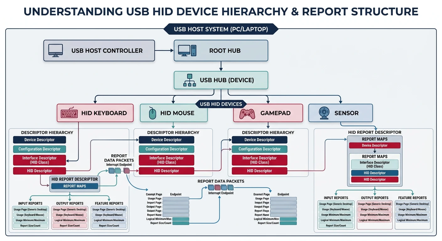
USB HID architecture — host controller enumeration, descriptors, and HID report parsing
Complexity Warning: A full USB stack is thousands of lines of code. Here we'll cover the concepts and provide a simplified overview. Most hobbyist OS projects rely on PS/2 emulation (BIOS legacy support) initially.
USB Basics
USB uses a hierarchical architecture with a host controller at the top:
╔═════════════════════════════════════════════════════════════════════════════╗║ USB ARCHITECTURE ║╠═════════════════════════════════════════════════════════════════════════════╣║║║┌───────────────────┐║║│ USB Host │║║│ Controller │║║│ (xHCI/EHCI/...) │║║└─────────┬─────────┘║║ │ ║║┌──────────────────┼──────────────────┐║║ │ │ │ ║║┌────┴────┐┌────┴────┐┌────┴────┐║║│ Root ││ USB ││ USB │║║│ Hub ││ Hub ││ Device │║║└────┬────┘└────┬────┘│(direct) │║║ │ │ └─────────┘║║┌─────┴─────┐┌────┴────┐║║ │ │ │ │ ║║┌────┴────┐┌────┴────┐┌──┴──┐║║│Keyboard ││ Mouse ││Flash│Devices identified by:║║│ HID ││ HID ││Drive│• Vendor ID (VID)║║└─────────┘└─────────┘└─────┘• Product ID (PID)║║• Class/Subclass/Protocol║║║╚═════════════════════════════════════════════════════════════════════════════╝
Controller
USB Speed
Era
Notes
UHCI
USB 1.x (12 Mbps)
Intel legacy
Simplest, schedule-based
OHCI
USB 1.x (12 Mbps)
Non-Intel legacy
Hardware does more work
EHCI
USB 2.0 (480 Mbps)
2000-2015
Companion controllers for 1.x
xHCI
USB 1.x-3.x
2010+
Modern unified controller
HID Protocol
HID devices describe their data format using Report Descriptors. A keyboard report might look like:
╔═════════════════════════════════════════════════════════════════════════════╗║ USB HID KEYBOARD REPORT (8 bytes) ║╠═════════════════════════════════════════════════════════════════════════════╣║║║┌──────┬──────┬──────┬──────┬──────┬──────┬──────┬──────┐║║│Mods│Rsrvd│Key 0│Key 1│Key 2│Key 3│Key 4│Key 5│║║└──────┴──────┴──────┴──────┴──────┴──────┴──────┴──────┘║║Byte 0 Byte 1 Byte 2 Byte 3 Byte 4 Byte 5 Byte 6 Byte 7║║║║Modifier Byte:Key Bytes (USB Usage IDs):║║Bit 0 = Left Ctrl 0x04 = 'a' ║║Bit 1 = Left Shift 0x05 = 'b' ║║Bit 2 = Left Alt ...║║Bit 3 = Left GUI (Win key) 0x1D = 'z' ║║Bit 4 = Right Ctrl 0x28 = Enter ║║Bit 5 = Right Shift 0x2C = Space ║║Bit 6 = Right Alt (Up to 6 simultaneous keys)║║Bit 7 = Right GUI ║║║╚═════════════════════════════════════════════════════════════════════════════╝
A minimal HID keyboard polling function (assuming USB stack is set up):
/* USB HID Keyboard Report */
typedef struct {
    uint8_t modifiers;      // Ctrl, Shift, Alt, GUI
    uint8_t reserved;       // Always 0
    uint8_t keys[6];        // Up to 6 keys pressed
} __attribute__((packed)) hid_keyboard_report_t;

/* USB HID Mouse Report */
typedef struct {
    uint8_t buttons;        // Button bits
    int8_t x;               // X movement (-127 to +127)
    int8_t y;               // Y movement
    int8_t wheel;           // Scroll wheel (optional)
} __attribute__((packed)) hid_mouse_report_t;

/* Process keyboard report */
void usb_keyboard_process(hid_keyboard_report_t* report) {
    // Check modifiers
    bool shift = (report->modifiers & 0x22);  // Left or right shift
    bool ctrl = (report->modifiers & 0x11);   // Left or right ctrl

    // Process each key
    for (int i = 0; i < 6; i++) {
        uint8_t usage = report->keys[i];
        if (usage == 0) continue;  // No key

        // Convert USB usage ID to ASCII (simplified)
        char c = 0;
        if (usage >= 0x04 && usage <= 0x1D) {
            c = 'a' + (usage - 0x04);
            if (shift) c = c - 'a' + 'A';
        } else if (usage >= 0x1E && usage <= 0x27) {
            c = '1' + (usage - 0x1E);
            if (usage == 0x27) c = '0';
        }

        if (c) keyboard_queue_char(c);
    }
}
Practical Approach: Most BIOS/UEFI systems provide PS/2 emulation for USB keyboards/mice. You can use our PS/2 drivers until you're ready to implement a full USB stack!
HPET Timer
The High Precision Event Timer (HPET) is a modern timer standard (Intel, 2004) that provides significantly higher resolution than the ancient PIT. Think of it as upgrading from a grandfather clock to an atomic clock!
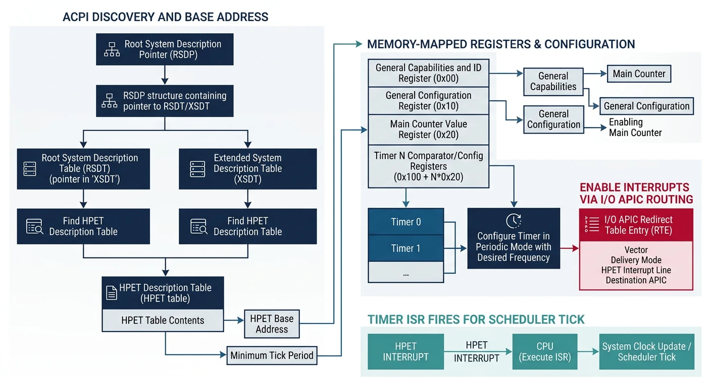
HPET timer — discovered through ACPI tables, providing 100ns resolution for precise scheduling
ACPI Discovery
The HPET is discovered through ACPI—there's a dedicated HPET table that tells us where the registers are mapped:
The HPET has a main counter that increments at a fixed frequency (typically 14.3 MHz or higher), plus multiple comparator timers that can trigger interrupts:
╔═════════════════════════════════════════════════════════════════════════════╗║ HPET ARCHITECTURE ║╠═════════════════════════════════════════════════════════════════════════════╣║║║┌─────────────────────────────────────────────────────────────────────┐║║│MAIN COUNTER (64-bit)│║║│Increments at period specified in CAPABILITIES register│║║│Typical: ~70 femtoseconds = ~14.3 MHz│║║└───────────────────────────────┬─────────────────────────────────────┘║║ │ ║║┌──────────────────┼──────────────────┐║║ │ │ │ ║║┌────┴────┐┌────┴────┐┌────┴────┐║║│ Timer 0 ││ Timer 1 ││ Timer 2 │(3-32 timers)║║│Comparatr││Comparatr││Comparatr│║║└────┬────┘└────┬────┘└────┬────┘║║ │ │ │ ║║ ▼ ▼ ▼ ║║┌─────────┐┌─────────┐┌─────────┐║║│ IRQ ││ IRQ ││ IRQ │║║│ (or MSI)││ (or MSI)││ (or MSI)│║║└─────────┘└─────────┘└─────────┘║║║║Each timer can be:║║• One-shot: Fire once when counter reaches comparator ║║• Periodic: Auto-reload comparator after fire ║║║╚═════════════════════════════════════════════════════════════════════════════╝
Register
Offset
Purpose
Capabilities
0x000
Period (bits 63-32), vendor ID, timer count
Configuration
0x010
Bit 0: Enable counter, Bit 1: Legacy mode
Main Counter
0x0F0
64-bit free-running counter
Timer N Config
0x100 + N*0x20
Timer mode, IRQ routing, enable
Timer N Comparator
0x108 + N*0x20
Value to compare against main counter
Here's how to set up a periodic timer using HPET:
/* HPET Timer N Configuration */
typedef struct {
    uint64_t config;        // Timer configuration
    uint64_t comparator;    // Comparator value
    uint64_t fsb_route;     // FSB interrupt routing (optional)
    uint64_t reserved;
} hpet_timer_t;

static uint64_t hpet_freq;  // Ticks per second

/* Get current time in nanoseconds */
uint64_t hpet_get_ns(void) {
    uint64_t ticks = hpet->main_counter;
    uint32_t period = hpet->capabilities >> 32;  // femtoseconds
    return (ticks * period) / 1000000;  // Convert to ns
}

/* Sleep for given microseconds */
void hpet_sleep_us(uint64_t us) {
    uint32_t period = hpet->capabilities >> 32;
    uint64_t ticks_to_wait = (us * 1000000000ULL) / period;
    uint64_t target = hpet->main_counter + ticks_to_wait;

    while (hpet->main_counter < target) {
        // Busy wait (or yield to scheduler in real OS)
    }
}

/* Set up periodic HPET interrupt (1ms) */
void hpet_setup_periodic(uint8_t timer_num, uint8_t irq) {
    hpet_timer_t* timer = (hpet_timer_t*)((uintptr_t)hpet + 0x100 + timer_num * 0x20);

    // Calculate ticks for 1ms
    uint32_t period = hpet->capabilities >> 32;
    uint64_t ticks_1ms = 1000000000000ULL / period;  // 1ms in ticks

    // Configure timer: periodic, level-triggered, enable interrupts
    timer->config = (irq << 9) |    // IRQ routing
                    (1 << 3) |       // Periodic mode
                    (1 << 2);        // Enable interrupts

    timer->comparator = hpet->main_counter + ticks_1ms;

    // Enable timer
    timer->config |= (1 << 2);
}
HPET vs PIT: HPET is ~70,000x more precise than the PIT at full resolution. Use HPET for high-resolution timing (games, multimedia), PIT for compatibility with older systems.
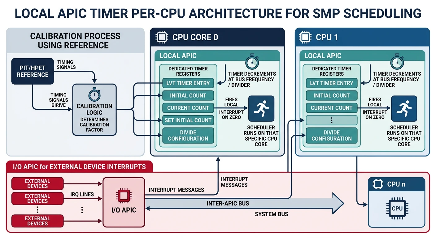
APIC Timer
The Local APIC Timer is a per-CPU timer built into every x86 processor (from Pentium onwards). Unlike the PIT or HPET which are system-wide, each CPU has its own APIC timer—perfect for SMP scheduling!
Local APIC timer — per-CPU timer built into each processor for symmetric multiprocessing
Local APIC
The Local APIC (Advanced Programmable Interrupt Controller) is part of the CPU itself. It handles interrupts locally and includes a built-in timer:
Unlike the PIT which runs at a known frequency (1.193182 MHz), the APIC timer's frequency depends on the CPU bus speed. We must calibrate it using a known time source:
Calibration Strategy: Start the APIC timer, wait a known time using PIT (or HPET), then calculate how many APIC ticks elapsed. This tells us the timer's actual frequency.
static uint32_t lapic_ticks_per_ms;  // Calibrated value

/* Calibrate APIC timer using PIT */
void lapic_timer_calibrate(void) {
    // Set divider to 16
    lapic_write(LAPIC_TIMER_DCR, 0x03);

    // Set initial count to max
    lapic_write(LAPIC_TIMER_ICR, 0xFFFFFFFF);

    // Wait 10ms using PIT
    pit_wait_ms(10);

    // Stop timer
    lapic_write(LAPIC_TIMER_LVT, 0x10000);

    // Calculate ticks per ms
    uint32_t elapsed = 0xFFFFFFFF - lapic_read(LAPIC_TIMER_CCR);
    lapic_ticks_per_ms = elapsed / 10;

    // Set up periodic timer (1ms interval)
    lapic_write(LAPIC_TIMER_LVT, 32 | 0x20000);  // Vector 32, periodic
    lapic_write(LAPIC_TIMER_DCR, 0x03);          // Divide by 16
    lapic_write(LAPIC_TIMER_ICR, lapic_ticks_per_ms);  // 1ms interval
}

/* Helper: Wait using PIT Channel 2 */
void pit_wait_ms(uint32_t ms) {
    // PIT frequency = 1193182 Hz
    // For ms milliseconds, need (1193182 / 1000) * ms ticks
    uint32_t ticks = (1193182 / 1000) * ms;

    // Configure PIT channel 2 for one-shot
    outb(0x61, (inb(0x61) & 0xFD) | 1);  // Enable gate
    outb(0x43, 0xB2);                     // Channel 2, mode 0
    outb(0x42, ticks & 0xFF);
    outb(0x42, ticks >> 8);

    // Wait for output to go high
    while (!(inb(0x61) & 0x20));
}
For SMP systems, each CPU needs its own timer. The APIC timer is perfect because each CPU's Local APIC has its own timer:
/* Initialize APIC timer on current CPU */
void lapic_timer_init_this_cpu(void) {
    // First CPU calibrates; others use the same value
    static bool calibrated = false;

    if (!calibrated) {
        lapic_timer_calibrate();
        calibrated = true;
    }

    // Set up periodic 1ms timer on this CPU
    lapic_write(LAPIC_TIMER_LVT, TIMER_VECTOR | 0x20000);  // Periodic
    lapic_write(LAPIC_TIMER_DCR, 0x03);                     // Divide by 16
    lapic_write(LAPIC_TIMER_ICR, lapic_ticks_per_ms);       // 1ms interval
}

/* Timer interrupt handler (runs on each CPU) */
void timer_handler(void) {
    // Update per-CPU tick counter
    cpu_local_t* cpu = get_cpu_local();
    cpu->ticks++;

    // Check if current process time slice expired
    if (current_process && --current_process->time_left == 0) {
        current_process->time_left = TIME_SLICE;
        schedule();  // Switch to next process
    }

    lapic_write(LAPIC_EOI, 0);  // End of interrupt
}
SMP Note: When using APIC timer for scheduling, remember to calibrate before bringing up other CPUs. TSC-deadline mode (modern CPUs) can avoid calibration entirely!
What You Can Build
Phase 14 Project: A fully interactive graphical OS! Your system now has mouse support for clicking windows, dragging, and GUI interaction. High-precision timers enable smooth animations and accurate scheduling.
Here's a complete demo that brings together mouse input and precision timing to create an interactive drawing application:
/* interactive_demo.c - Mouse + Timing Demo */
#include "mouse.h"
#include "hpet.h"
#include "graphics.h"

#define CANVAS_X 50
#define CANVAS_Y 50
#define CANVAS_W 700
#define CANVAS_H 500

typedef struct {
    uint32_t fg_color;
    uint32_t bg_color;
    int brush_size;
    bool drawing;
    uint64_t last_frame_time;
    uint32_t frame_count;
    uint32_t fps;
} app_state_t;

app_state_t app = {
    .fg_color = 0x000000,
    .bg_color = 0xFFFFFF,
    .brush_size = 3,
    .drawing = false
};

/* Color palette */
uint32_t palette[] = {
    0x000000, 0xFF0000, 0x00FF00, 0x0000FF,
    0xFFFF00, 0xFF00FF, 0x00FFFF, 0xFFFFFF
};

void draw_toolbar(void) {
    // Draw palette
    for (int i = 0; i < 8; i++) {
        int x = 10 + i * 35;
        fill_rect(x, 10, 30, 30, palette[i]);
        draw_rect(x, 10, 30, 30, 0x000000);
    }

    // Draw brush size indicator
    draw_printf(320, 15, 0x000000, "Brush: %d", app.brush_size);

    // Draw FPS counter
    draw_printf(450, 15, 0x008000, "FPS: %d", app.fps);

    // Draw canvas border
    draw_rect(CANVAS_X - 1, CANVAS_Y - 1, CANVAS_W + 2, CANVAS_H + 2, 0x000000);
}

void handle_mouse_click(int x, int y) {
    // Check palette clicks
    for (int i = 0; i < 8; i++) {
        int px = 10 + i * 35;
        if (x >= px && x < px + 30 && y >= 10 && y < 40) {
            app.fg_color = palette[i];
            return;
        }
    }
}

void draw_brush(int x, int y) {
    // Only draw inside canvas
    if (x < CANVAS_X || x >= CANVAS_X + CANVAS_W ||
        y < CANVAS_Y || y >= CANVAS_Y + CANVAS_H) {
        return;
    }

    // Draw filled circle at cursor
    fill_circle(x, y, app.brush_size, app.fg_color);
}

void update_fps(void) {
    uint64_t now = hpet_get_ns();
    app.frame_count++;

    // Update FPS every second
    if (now - app.last_frame_time >= 1000000000ULL) {
        app.fps = app.frame_count;
        app.frame_count = 0;
        app.last_frame_time = now;
    }
}

void interactive_demo(void) {
    // Initialize subsystems
    graphics_init();
    mouse_init();
    hpet_init_from_acpi();

    // Clear canvas
    fill_rect(CANVAS_X, CANVAS_Y, CANVAS_W, CANVAS_H, app.bg_color);
    draw_toolbar();

    app.last_frame_time = hpet_get_ns();

    while (1) {
        // Process mouse state
        int mx = mouse.x, my = mouse.y;
        uint8_t buttons = mouse.buttons;

        // Handle left button for drawing
        if (buttons & 0x01) {
            if (!app.drawing) {
                handle_mouse_click(mx, my);
                app.drawing = true;
            }
            draw_brush(mx, my);
        } else {
            app.drawing = false;
        }

        // Handle right button for eraser
        if (buttons & 0x02) {
            uint32_t old_color = app.fg_color;
            app.fg_color = app.bg_color;
            draw_brush(mx, my);
            app.fg_color = old_color;
        }

        // Handle middle button for brush size
        static bool mid_pressed = false;
        if ((buttons & 0x04) && !mid_pressed) {
            app.brush_size = (app.brush_size % 10) + 1;
            mid_pressed = true;
            draw_toolbar();
        } else if (!(buttons & 0x04)) {
            mid_pressed = false;
        }

        // Draw cursor
        draw_rect(mx - 1, my - 1, 3, 3, 0xFF0000);

        // Update display
        gfx_flip();
        update_fps();

        // Cap frame rate to 60 FPS (~16.7ms per frame)
        hpet_sleep_us(16667);
    }
}
Exercises
Exercise 1: Scroll Wheel Support
InputMedium
Extend the PS/2 mouse driver to support scroll wheel (IntelliMouse protocol):
Send the "magic sequence" (set sample rate: 200, 100, 80) to enable scroll wheel
Mouse packets become 4 bytes (byte 3 = scroll delta)
Handle the Z-axis data in your mouse handler
Test by zooming in/out on the canvas
// Enable IntelliMouse scroll wheel
void mouse_enable_scroll(void) {
    mouse_set_sample_rate(200);
    mouse_set_sample_rate(100);
    mouse_set_sample_rate(80);
    // Now packets are 4 bytes with scroll in byte 3
}
Exercise 2: Animation System
TimingMedium
Create a simple animation system using HPET for timing:
Define an animation_t struct with start_time, duration, start_value, end_value
Implement animation_update() to calculate current value based on elapsed time
Support easing functions (linear, ease-in, ease-out)
Animate a window moving across the screen at 60 FPS
Record timestamp of each click using hpet_get_ns()
If two clicks are within 500ms and 5 pixels of each other, it's a double-click
Generate separate events for single-click, double-click, and triple-click
Test by double-clicking to select words in a text editor
// Double-click detection state
typedef struct {
    uint64_t last_click_time;
    int last_click_x, last_click_y;
    int click_count;
} click_state_t;
Next Steps
With input and timing in place, your OS is now truly interactive! In Phase 15, we'll discover and interact with hardware—enumerating PCI devices, writing device drivers, and accessing modern storage like NVMe.