We use cookies to enhance your browsing experience, serve personalized content, and analyze our traffic.
By clicking "Accept All", you consent to our use of cookies. See our
Privacy Policy
for more information.
Phase 11 Goals: By the end of this phase, your kernel will run in 64-bit long mode. You'll have 4-level paging for huge address spaces, expanded 64-bit registers, and access to modern CPU features.
Key Insight: 64-bit mode isn't just about more memory—it brings more registers, a simpler segment model, and mandatory paging that actually simplifies many aspects of kernel development.
x86 CPU Modes Evolution:┌─────────────────────────────────────────────────────────────────┐│ CPU History │├───────────┬───────────────────────────────────────────────────┤│ 8086 │ Real Mode (16-bit, 1MB) 1978 │├───────────┼───────────────────────────────────────────────────┤│ 80386 │ Protected Mode (32-bit, 4GB) 1985 │├───────────┼───────────────────────────────────────────────────┤│ AMD64 │ Long Mode (64-bit, 256TB) 2003 │ ← We're here!
└───────────┴───────────────────────────────────────────────────┘Memory Addressing Comparison:32-bit Protected Mode: 64-bit Long Mode:┌──────────────────┐ ┌──────────────────────────────┐│ │ │ ││ 4 GB Max │ │ 256 TB Virtual ││ (2³² bytes) │ │ (2⁴⁸ bytes*) ││ │ │ ││ ┌────────────┐ │ │ ┌────────────────────────┐ ││ │ User Space │ │ │ │ User Space │ ││ │ 3 GB │ │ │ │ 128 TB │ ││ ├────────────┤ │ │ ├────────────────────────┤ ││ │ Kernel │ │ │ │ Kernel │ ││ │ 1 GB │ │ │ │ 128 TB │ ││ └────────────┘ │ │ └────────────────────────┘ │└──────────────────┘ └──────────────────────────────┘* Current implementations use 48 bits; architecture supports 57 bits (128PB)
Why 64-Bit?
64-bit mode provides significant advantages beyond just addressing more memory:
Feature
32-Bit Mode
64-Bit Mode
Benefit
General Purpose Registers
8 (EAX-EDI)
16 (RAX-R15)
More data in registers, fewer memory accesses
Register Width
32 bits
64 bits
Larger values without multi-precision math
Virtual Address Space
4 GB
256 TB
Room for big data, memory-mapped files
Calling Convention
Stack-based
Register-based
Faster function calls, no stack bouncing
Instruction Pointer
RIP-relative: manual
RIP-relative addressing
Position-independent code easier
Segment Registers
Active (GDT required)
Mostly ignored (flat model)
Simpler memory model
Real-World Impact
Why 4GB Isn't Enough
Modern applications easily exceed 32-bit limits:
Web browser - Chrome/Firefox can use 2-4 GB per tab
Video editing - 4K footage needs 8+ GB for editing
Databases - In-memory caching requires huge RAM
Machine learning - Model training uses 16-64+ GB
The 4GB limit of 32-bit mode became a serious constraint by mid-2000s.
MotivationMemory
Architecture Overview
The transition from 32-bit to 64-bit involves several CPU and OS changes:
Long Mode Sub-Modes:┌─────────────────────────────────────────────────────────────────┐│ Long Mode (IA-32e) │├─────────────────────────────────┬───────────────────────────────┤│ 64-Bit Mode │ Compatibility Mode ││ (Native 64-bit code) │ (Run 32-bit code) ││ │ ││ • Full 64-bit registers │ • 32-bit registers only ││ • 64-bit pointers │ • 32-bit pointers ││ • New instruction encodings │ • Original instruction set ││ • RIP-relative addressing │ • Same as protected mode │└─────────────────────────────────┴───────────────────────────────┘Compatibility mode allows running 32-bit apps on 64-bit kernel!
AMD vs Intel: AMD created x86-64 (AMD64) in 2003. Intel later adopted it as "Intel 64" or "EM64T". They're compatible—your code works on both. We use "x86-64" or "long mode" to refer to the architecture.
CPU Detection
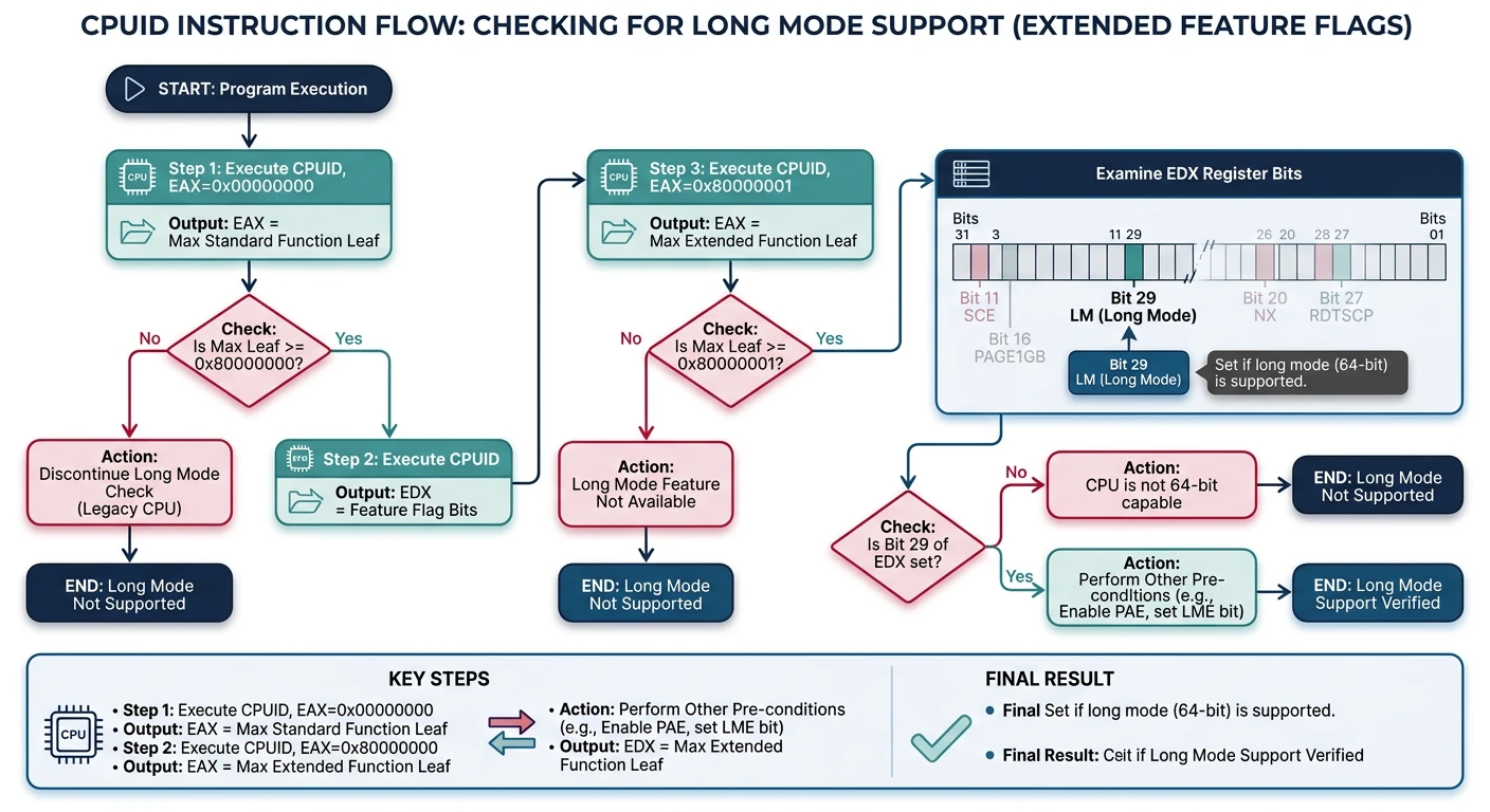
Before switching to 64-bit mode, we must verify the CPU supports it. Not all x86 processors have long mode—older 32-bit-only CPUs don't. The CPUID instruction tells us what features are available.
Long mode detection using CPUID: verify CPUID availability, check extended leaf support, then test bit 29 of EDX from leaf 0x80000001
CPUID Instruction
CPUID is x86's feature discovery mechanism. You put a "leaf" number in EAX, execute CPUID, and get feature flags back in EAX/EBX/ECX/EDX:
CPUID Leaf
Information Returned
Key Bits
EAX=0
Vendor string, max leaf
"GenuineIntel" or "AuthenticAMD"
EAX=1
Feature flags
SSE, SSE2, PAE, PSE, etc.
EAX=0x80000000
Extended leaf max
Check if extended features exist
EAX=0x80000001
Extended features
Long Mode (bit 29 of EDX)
CPUID Support: CPUID itself isn't available on pre-486 CPUs! You must first check if the EFLAGS.ID bit (bit 21) can be toggled. If it can, CPUID is supported.
Checking Support
Here's the complete sequence to verify long mode is available:
; Check for long mode support
check_long_mode:
    ; Check if CPUID is supported
    pushfd
    pop eax
    mov ecx, eax
    xor eax, 1 << 21    ; Flip ID bit
    push eax
    popfd
    pushfd
    pop eax
    push ecx
    popfd
    cmp eax, ecx
    je .no_cpuid

    ; Check for extended CPUID
    mov eax, 0x80000000
    cpuid
    cmp eax, 0x80000001
    jb .no_long_mode

    ; Check for long mode
    mov eax, 0x80000001
    cpuid
    test edx, 1 << 29   ; Long mode bit
    jz .no_long_mode

    mov eax, 1          ; Long mode supported
    ret

.no_cpuid:
.no_long_mode:
    xor eax, eax        ; Long mode not supported
    ret
Detection steps explained:
Check CPUID support - Toggle EFLAGS.ID bit. If it toggles, CPUID exists
Check extended leaves - Call CPUID with EAX=0x80000000 to see if 0x80000001 is supported
Check long mode bit - Call CPUID with EAX=0x80000001, check EDX bit 29
Graceful Fallback: If long mode isn't supported, you have options: run as 32-bit OS, show error message, or use PAE for >4GB RAM in 32-bit mode. Don't just crash!
64-Bit GDT
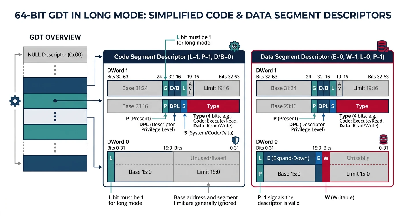
Long mode still requires a GDT, but it's much simpler. Most segment fields are ignored—the CPU uses a flat memory model. We only need to set a few specific bits.
Simplified 64-bit GDT: long mode ignores most segment fields, requiring only the L (long mode), P (present), and S (code/data) bits for code segments
GDT Structure
64-Bit GDT Entry (8 bytes):Bit: 63 0 ┌────┬───┬───┬───┬────┬─────────────────────────────────┐ │ G │ D │ L │AVL│Seg │ (Ignored in 64-bit) │ │ │ B │ │ │Lim │ │ ├────┼───┼───┼───┼────┼───┬───┬───┬───┬────────────────┤Byte: │ 7 │ │ │ │ 6 │ P │DPL│ S │Type│ 5-0 │ └────┴───┴───┴───┴────┴───┴───┴───┴───┴────────────────┘For 64-bit code segment: L = 1 (Long mode) D = 0 (Must be 0 when L=1) P = 1 (Present) S = 1 (Code/data, not system)Type = 0xA (Execute/Read)Result: The code segment is just a few bits set!
Still need valid selectors but base doesn't matter
FS, GS
Base IS used
Used for thread-local storage, CPU-local data
Why FS/GS matter: Linux uses GS for kernel per-CPU data and FS for thread-local storage. Windows uses the opposite convention. The MSR_GS_BASE and MSR_FS_BASE registers set the base address directly, bypassing the GDT.
4-Level Paging
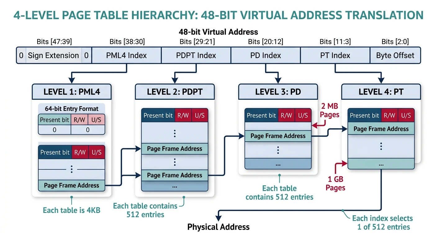
Long mode requires paging—you can't run without it. And it uses 4-level paging (instead of 32-bit's 2-level) to address the huge 48-bit virtual address space.
4-level paging structure: CR3 points to PML4, each level uses 9 bits of the virtual address to index 512 entries, translating 48-bit addresses to physical frames
During the transition to long mode, we need identity mapping—where virtual address equals physical address. Why? Because when we enable paging, the instruction pointer suddenly becomes a virtual address. If that virtual address isn't mapped to where the code actually is, we crash.
Identity Mapping for Boot:Physical: 0x00000000 ─────────────────────► 0x40000000 (1GB) │ │ │ 1:1 Mapping │ │ │Virtual: 0x00000000 ─────────────────────► 0x40000000 (1GB)After boot, you might want a higher-half kernel:Physical: 0x00000000 ──────────────────► 0x40000000 │ │ Mapped to TWO places: │Virtual: 0x00000000 (identity, temporary) 0xFFFF800000000000 (higher-half kernel)
Higher-Half Kernel: Most 64-bit kernels map themselves at the top of the address space (like 0xFFFF8000_00000000). This leaves the entire lower half for user space. We start with identity mapping, then add the higher-half mapping, then remove the identity mapping.
Mode Transition
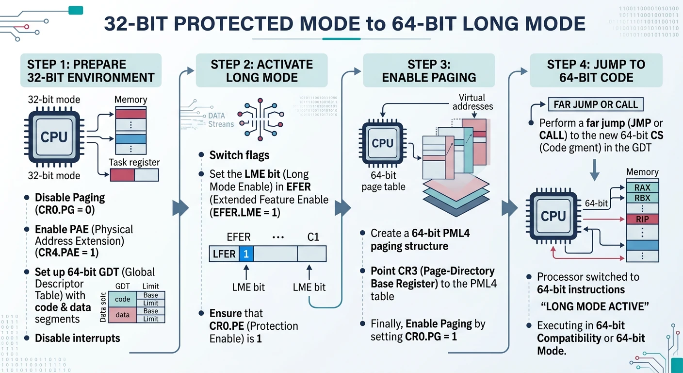
The transition from 32-bit protected mode to 64-bit long mode requires a specific sequence. You can't just flip a switch—several CPU features must be enabled in order.
Long mode transition sequence: disable paging, load PML4 into CR3, enable PAE, set EFER.LME, enable paging, then far jump to 64-bit code segment
PAE (Physical Address Extension) is required for long mode. It changes the page table format from 32-bit entries to 64-bit entries, which is the basis for 4-level paging:
; Enable PAE (required for long mode)
mov eax, cr4
or eax, 1 << 5      ; Set PAE bit (bit 5)
mov cr4, eax
Order Matters! You must enable PAE before enabling long mode. The CPU checks PAE when you set EFER.LME. If PAE isn't enabled, it triggers a general protection fault.
Enable Long Mode
Long mode is enabled through the EFER (Extended Feature Enable Register) MSR. This is a model-specific register accessed with RDMSR/WRMSR:
; Transition to long mode
enable_long_mode:
    ; Disable paging first
    mov eax, cr0
    and eax, ~(1 << 31)
    mov cr0, eax

    ; Load P4 table address
    mov eax, p4_table
    mov cr3, eax

    ; Enable PAE
    mov eax, cr4
    or eax, 1 << 5      ; PAE bit
    mov cr4, eax

    ; Enable long mode in EFER MSR
    mov ecx, 0xC0000080 ; EFER MSR
    rdmsr
    or eax, 1 << 8      ; LM bit
    wrmsr

    ; Enable paging
    mov eax, cr0
    or eax, 1 << 31     ; PG bit
    mov cr0, eax

    ret
EFER Bit
Name
Purpose
Bit 0
SCE
System Call Extensions (enables SYSCALL/SYSRET)
Bit 8
LME
Long Mode Enable - Set this to enter long mode
Bit 10
LMA
Long Mode Active - CPU sets this (read-only)
Bit 11
NXE
No-Execute Enable (for W^X security)
Jump to 64-Bit
After enabling paging with long mode active, we're technically in "compatibility mode" until we load a 64-bit code segment. A far jump loads the new GDT and switches to true 64-bit mode:
Success! After the far jump, you're in 64-bit mode. The instruction pointer is now 64 bits, registers are 64 bits, and you can access the full address space. The "OK" printed to the screen confirms the transition worked.
64-Bit Kernel Code
With 64-bit mode active, you'll write kernel code in 64-bit C. But there are important differences from 32-bit code.
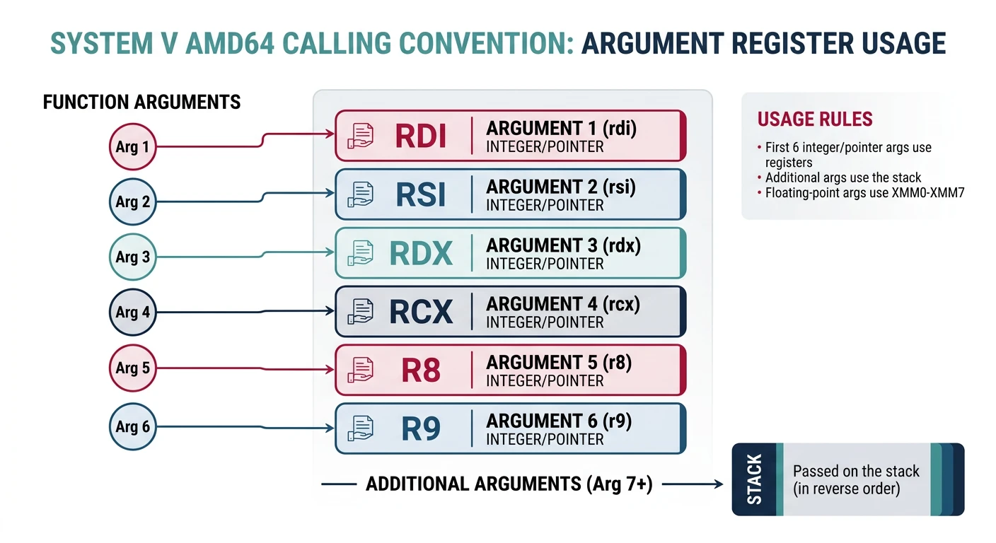
System V AMD64 calling convention: first six integer arguments pass in registers (RDI, RSI, RDX, RCX, R8, R9), with return value in RAX
Calling Convention
The System V AMD64 ABI (used on Linux, BSD, macOS) passes arguments in registers, not on the stack:
When converting 32-bit kernel code to 64-bit, watch for these common issues:
Issue
32-Bit
64-Bit
Fix
Pointer size
4 bytes
8 bytes
Use size_t, uintptr_t for pointer math
long size
4 bytes
8 bytes (Unix)
Use explicit types: uint32_t, uint64_t
Stack alignment
4-byte
16-byte before CALL
Assembly must maintain alignment
IDT entry size
8 bytes
16 bytes
Rewrite IDT structures
Inline assembly
32-bit registers
64-bit registers
EAX → RAX, etc.
Code Pattern
64-Bit Portable Structures
/* Portable types for 64-bit */
#include

// Page table entry - always 64-bit in long mode
typedef uint64_t pte_t;

// Physical addresses can be 52-bit
typedef uint64_t phys_addr_t;

// Virtual addresses are 64-bit (48 used)
typedef uintptr_t virt_addr_t;

// Use size_t for sizes and counts
size_t num_pages = mem_size / PAGE_SIZE;

/* 64-bit IDT entry structure */
typedef struct {
    uint16_t offset_low;      // Bits 0-15
    uint16_t selector;        // Code segment selector
    uint8_t  ist;             // Interrupt Stack Table
    uint8_t  type_attr;       // Type and attributes
    uint16_t offset_mid;      // Bits 16-31
    uint32_t offset_high;     // Bits 32-63  ← NEW!
    uint32_t reserved;        // Must be 0    ← NEW!
} __attribute__((packed)) idt64_entry_t;
PortabilityTypes
Compiler Flags: Compile 64-bit kernel code with: gcc -m64 -mcmodel=large -mno-red-zone -fno-pic. The -mno-red-zone is critical for interrupt handlers—without it, interrupts corrupt the stack!
What You Can Build
Phase 11 Milestone: A 64-bit operating system! Your kernel now runs in long mode with 4-level paging, expanded registers, and access to modern CPU features. You're ready for modern hardware and can address terabytes of memory.
Complete 64-Bit Boot Sequence
; boot64.asm - Complete boot to 64-bit mode
[BITS 32]
section .text
global _start

_start:
    ; We're in 32-bit protected mode from bootloader

    ; 1. Check long mode support
    call check_long_mode
    test eax, eax
    jz .no_long_mode

    ; 2. Set up 4-level page tables
    call setup_page_tables

    ; 3. Enable PAE
    mov eax, cr4
    or eax, 1 << 5
    mov cr4, eax

    ; 4. Load PML4 into CR3
    mov eax, p4_table
    mov cr3, eax

    ; 5. Enable Long Mode in EFER
    mov ecx, 0xC0000080
    rdmsr
    or eax, 1 << 8
    wrmsr

    ; 6. Enable paging (enters compatibility mode)
    mov eax, cr0
    or eax, 1 << 31
    mov cr0, eax

    ; 7. Load 64-bit GDT and far jump
    lgdt [gdt64.pointer]
    jmp gdt64.code:long_mode_entry

.no_long_mode:
    ; Print error and halt
    mov dword [0xB8000], 0x4F524F45  ; "ER"
    mov dword [0xB8004], 0x4F3A4F52  ; "R:"
    hlt

[BITS 64]
long_mode_entry:
    ; Reload segment registers
    mov ax, gdt64.data
    mov ds, ax
    mov es, ax
    mov fs, ax
    mov gs, ax
    mov ss, ax

    ; Set up stack
    mov rsp, stack_top

    ; Call C kernel
    extern kernel_main
    call kernel_main

    ; Halt
    cli
    hlt

section .bss
align 16
stack_bottom:
    resb 16384
stack_top:
Exercises
Exercise 1
Higher-Half Kernel
Map your kernel at the higher half of the address space:
Keep identity mapping for boot transition
Add second mapping at 0xFFFF800000000000
Update kernel linker script to use higher-half addresses
After transition, remove identity mapping
; Map same physical memory to high address
mov rax, p3_table
or rax, 0b11
mov [p4_table + 256 * 8], rax  ; PML4[256] = high half
MemoryLayout
Exercise 2
NX (No-Execute) Protection
Enable no-execute bit for data pages:
Set EFER.NXE bit to enable NX feature
Mark code pages as executable (bit 63 = 0)
Mark data/stack pages as non-executable (bit 63 = 1)
Test: Try executing code from stack—should fault!
// Set NX bit on data page entry
pte |= (1ULL << 63);  // No execute
SecurityW^X
Exercise 3
SYSCALL/SYSRET
Replace interrupt-based syscalls with SYSCALL instruction:
Modern CPUs support 5-level paging (57-bit addresses):
Check CPUID for la57 support (leaf 7, ECX bit 16)
Create PML5 table pointing to PML4
Set CR4.LA57 before enabling paging
Address space grows to 128 PB!
Note: 5-level paging is only needed for massive server workloads. 4-level (256TB) is plenty for most systems.
AdvancedModern CPUs
Next Steps
Congratulations! Your kernel now runs in 64-bit mode with access to modern CPU features. But we're still booting via legacy BIOS. In Phase 12, we'll modernize the boot process with UEFI.
BIOS vs UEFI Boot:Legacy BIOS (Current): UEFI (Next Phase):┌─────────────────────┐ ┌─────────────────────────┐│ 16-bit Real Mode │ │ 64-bit from start! ││ 512-byte bootloader│ │ Full FAT32 filesystem ││ MBR partitioning │ │ GPT partitioning ││ No graphics │ │ GOP framebuffer ││ Manual A20 gate │ │ Modern memory map │└─────────────────────┘ └─────────────────────────┘
Key Takeaways
CPUID before transition - Always verify long mode support before attempting switch
PAE is mandatory - Long mode requires PAE-style page tables
Modern Architecture! Your OS now runs on the same CPU mode as Windows, Linux, and macOS. You have access to 16 general-purpose registers, terabytes of address space, and modern security features like NX bit. The foundation is complete!