Back to Technology

Phase 15: Hardware Discovery & Drivers

February 6, 2026 Wasil Zafar 35 min read

Discover hardware through PCI enumeration, write device drivers, and implement modern storage through AHCI and NVMe interfaces.

Table of Contents

  1. Introduction
  2. PCI Enumeration
  3. Driver Framework
  4. AHCI Storage
  5. NVMe Storage
  6. What You Can Build
  7. Next Steps

Introduction: Hardware Discovery

Phase 15 Goals: By the end of this phase, your OS will discover hardware through PCI enumeration, have a driver framework, and support modern storage via AHCI (SATA) and NVMe.

Your OS is now graphical and interactive. But all that software runs on hardware—and modern PCs have a lot of it! How does your OS know what devices are connected? How does it talk to an SSD, a network card, or a GPU?

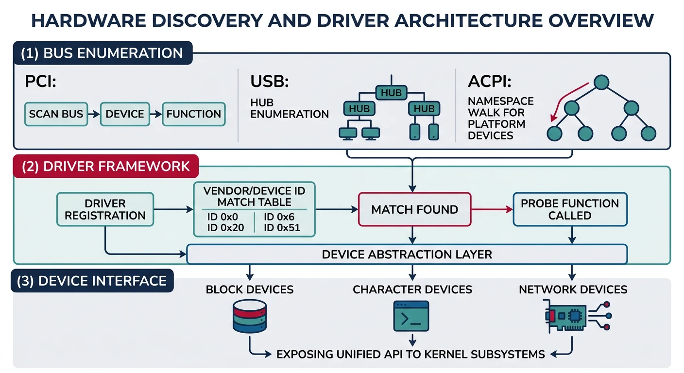
The answer is a two-part system: hardware discovery (finding what's connected) and device drivers (knowing how to talk to each device). This phase covers both.

╔═════════════════════════════════════════════════════════════════════════════╗
              HARDWARE DISCOVERY & DRIVER ARCHITECTURE                       
╠═════════════════════════════════════════════════════════════════════════════╣
                                                                             
  Application Layer                                                        
  ┌─────────────┐  ┌─────────────┐  ┌─────────────┐                        
  │ File System │  │  Network    │  │   Graphics  │                        
  │   (VFS)     │  │   Stack     │  │   Subsystem │                        
  └──────┬──────┘  └──────┬──────┘  └──────┬──────┘                        
         │               │               │                                  
  ───────┴───────────────┴───────────────┴───────                          
                                                                             
  Driver Layer                                                             
  ┌─────────────┐  ┌─────────────┐  ┌─────────────┐  ┌─────────────┐       
   NVMe Driver │  │ AHCI Driver │  │ NIC Driver  │  │ GPU Driver         
  └──────┬──────┘  └──────┬──────┘  └──────┬──────┘  └──────┬──────┘       
         │               │               │               │                 
  ───────┴───────────────┴───────────────┴───────────────┴─────            
                                                                             
  PCI/PCIe Bus Layer                                                       
  ┌─────────────────────────────────────────────────────────────────────┐   
    PCI Enumeration + Configuration                                        
    • Scan Bus:Slot:Function                                              
    • Read Vendor/Device IDs                                              
    • Map BARs (Memory/IO)                                                
    • Match to Drivers                                                    
  └─────────────────────────────────────────────────────────────────────┘   
                                                                             
  Physical Hardware                                                        
  ┌────────┐  ┌────────┐  ┌────────┐  ┌────────┐  ┌────────┐               
  │ NVMe   │  │ SATA   │  │ Intel  │  │ RTX    │  │ USB    │               
  │ SSD    │  │ SSD/HD │  │ NIC    │  │ GPU    │  │ Ctrl   │               
  └────────┘  └────────┘  └────────┘  └────────┘  └────────┘               
                                                                             
╚═════════════════════════════════════════════════════════════════════════════╝
Key Insight: Hardware discovery is the foundation of extensibility. PCI enumeration lets your OS find and configure devices automatically, while a proper driver framework allows modular hardware support.

Hardware Landscape

Modern PCs communicate with hardware through several interfaces:

Bus Typical Devices Speed Discovery
PCI/PCIe GPUs, NICs, NVMe SSDs, SATA controllers Up to 64 GB/s (PCIe 5.0 x16) Configuration Space scan
USB Keyboards, mice, storage, cameras Up to 20 Gbps (USB 3.2) Hub enumeration
SATA HDDs, older SSDs, optical drives 6 Gbps (SATA III) Port detection via AHCI
LPC Legacy devices (PS/2, TPM) ~33 MHz ACPI/Hardcoded

For this phase, we focus on PCI/PCIe enumeration—the primary discovery mechanism for high-performance devices.

Driver Model

A driver is software that knows how to "speak" a specific device's protocol. Good OS design separates:

╔═════════════════════════════════════════════════════════════════════════════╗
                         OS DRIVER MODEL                                     
╠═════════════════════════════════════════════════════════════════════════════╣
                                                                             
  ┌─────────────────────────────────────────────────────────────────────┐   
                        Generic Block Device API                           
    read_blocks(), write_blocks(), get_info()                             
  └─────────────────────────────┬───────────────────────────────────────┘   

           ┌───────────────────┼───────────────────┐                        
           │                   │                   │                        
  ┌────────┴────────┐  ┌────────┴────────┐  ┌────────┴────────┐            
   NVMe Driver      │  │ AHCI Driver      │  │ IDE Driver                   
   Implements API  │  │ Implements API  │  │ Implements API              
   for NVMe SSDs   │  │ for SATA        │  │ for legacy IDE              
  └─────────────────┘  └─────────────────┘  └─────────────────┘            
                                                                             
  Benefits:                                                                
  • File system doesn't care which storage technology is used              
  • New drivers can be added without changing upper layers                  
  • Same code works on any hardware that has a driver                       
                                                                             
╚═════════════════════════════════════════════════════════════════════════════╝

This abstraction is critical. Your file system calls block_read(), and the driver translates that to the specific commands the hardware understands.

Driver Lifecycle:
  1. Registration - Driver tells the kernel what devices it supports
  2. Probe - Kernel asks "can you handle this device?"
  3. Attach - Driver initializes the hardware
  4. Operation - Driver handles requests
  5. Detach - Cleanup when device removed (hot-unplug)

PCI Enumeration

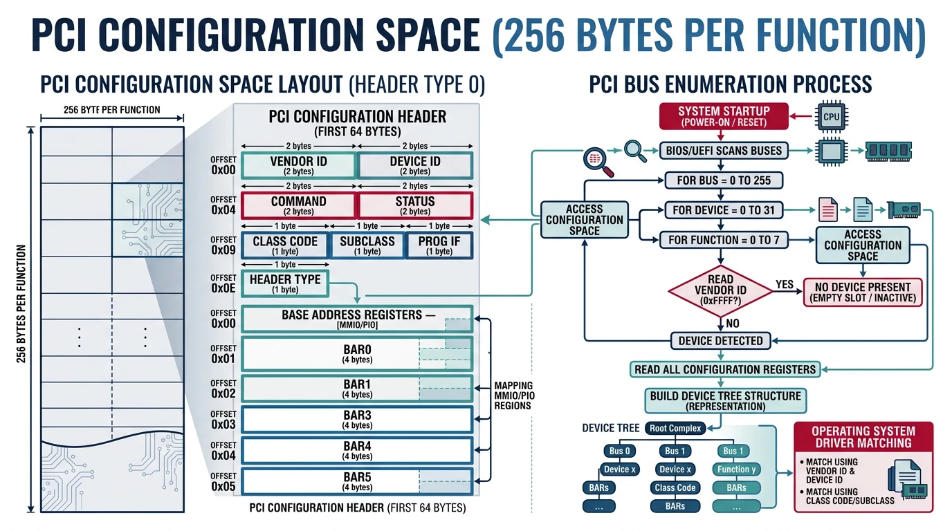
PCI (Peripheral Component Interconnect) is the standard bus for high-speed devices. Every PCI device has a 256-byte Configuration Space that describes what it is and how to talk to it.

╔═════════════════════════════════════════════════════════════════════════════╗
                         PCI BUS TOPOLOGY                                    
╠═════════════════════════════════════════════════════════════════════════════╣
                                                                             
                    CPU                                                      

              ┌──────┴──────┐                                                
                Host Bridge    (Root Complex)                             
              └──────┬──────┘                                                

        ═══════════════════════════════════════  Bus 0                     
              │           │           │                                      
        ┌─────┴────┐ ┌────┴────┐ ┌────┴────┐                                
          GPU     │ │PCI-PCI │ │ AHCI                                    
        00:02.0  │ │ Bridge │ │00:1f.2                                 
        └──────────┘ └────┬────┘ └─────────┘                                

                ═════════════════════════  Bus 1                            
                     │           │                                           
               ┌─────┴────┐ ┌────┴────┐                                      
                 NVMe    │ │  NIC                                          
               01:00.0  │ │01:00.1                                       
               └──────────┘ └─────────┘                                      
                                                                             
  Address Format: Bus:Slot.Function (e.g., 00:1f.2 = Bus 0, Slot 31, Func 2)
                                                                             
╚═════════════════════════════════════════════════════════════════════════════╝

Configuration Space

Every PCI device has a 256-byte Configuration Space (4KB for PCIe). The first 64 bytes are standardized:

╔═════════════════════════════════════════════════════════════════════════════╗
                PCI CONFIGURATION SPACE HEADER (Type 0)                      
╠═════════════════════════════════════════════════════════════════════════════╣
                                                                             
  Offset    31            16 15             0                               
  ┌────────┬───────────────┬───────────────┐                               
   0x00      Device ID       Vendor ID     ← Identity              
  ├────────┼───────────────┼───────────────┤                               
   0x04       Status        Command       ← Control               
  ├────────┼───────────────┴───────────────┤                               
   0x08   ClassSubClsProgIF   Rev ID       ← Classification        
  ├────────┼───────────────────────────────┤                               
   0x0C   BISTHdrTypLatCacheLine      ← Built-in test          
  ├────────┼───────────────────────────────┤                               
   0x10             BAR0                 ← Base Address Registers 
  ├────────┼───────────────────────────────┤                               
   0x14             BAR1                                            
  ├────────┼───────────────────────────────┤                               
   0x18             BAR2                                            
  ├────────┼───────────────────────────────┤                               
   0x1C             BAR3                                            
  ├────────┼───────────────────────────────┤                               
   0x20             BAR4                                            
  ├────────┼───────────────────────────────┤                               
   0x24             BAR5                 ← Total 6 BARs          
  ├────────┼───────────────────────────────┤                               
   ...              ...                                             
  ├────────┼───────────────┬───────────────┤                               
   0x3C      Max_Lat      IRQ Line     ← Interrupt info       
  └────────┴───────────────┴───────────────┘                               
                                                                             
╚═════════════════════════════════════════════════════════════════════════════╝

Access Configuration Space via I/O ports on legacy PCI:

/* PCI Configuration Space Access */
#define PCI_CONFIG_ADDR 0xCF8
#define PCI_CONFIG_DATA 0xCFC

/* Read 32-bit value from PCI config space */
uint32_t pci_read(uint8_t bus, uint8_t slot, uint8_t func, uint8_t offset) {
    uint32_t address = (1U << 31)           // Enable bit
                     | ((uint32_t)bus << 16)
                     | ((uint32_t)slot << 11)
                     | ((uint32_t)func << 8)
                     | (offset & 0xFC);
    
    outl(PCI_CONFIG_ADDR, address);
    return inl(PCI_CONFIG_DATA);
}

/* Write 32-bit value to PCI config space */
void pci_write(uint8_t bus, uint8_t slot, uint8_t func, 
               uint8_t offset, uint32_t value) {
    uint32_t address = (1U << 31)
                     | ((uint32_t)bus << 16)
                     | ((uint32_t)slot << 11)
                     | ((uint32_t)func << 8)
                     | (offset & 0xFC);
    
    outl(PCI_CONFIG_ADDR, address);
    outl(PCI_CONFIG_DATA, value);
}

Common Class Codes help identify device types:

Class Subclass Description
0x01 0x06 SATA Controller (AHCI)
0x01 0x08 Non-Volatile Memory (NVMe)
0x02 0x00 Ethernet Controller
0x03 0x00 VGA Compatible Controller
0x0C 0x03 USB Controller

Bus Scanning

To discover all devices, scan every Bus:Slot:Function combination. If Vendor ID is 0xFFFF, no device is present:

/* PCI Device Structure */
typedef struct pci_device {
    uint8_t  bus, slot, func;
    uint16_t vendor_id;
    uint16_t device_id;
    uint8_t  class_code;
    uint8_t  subclass;
    uint8_t  prog_if;
    uint32_t bar[6];
    uint8_t  interrupt_line;
    struct pci_device* next;
} pci_device_t;

pci_device_t* pci_devices = NULL;

/* Scan all PCI buses */
void pci_scan(void) {
    for (uint16_t bus = 0; bus < 256; bus++) {
        for (uint8_t slot = 0; slot < 32; slot++) {
            for (uint8_t func = 0; func < 8; func++) {
                uint32_t id = pci_read(bus, slot, func, 0);
                uint16_t vendor = id & 0xFFFF;
                
                if (vendor == 0xFFFF) continue;  // No device
                
                // Found device - add to list
                pci_device_t* dev = kmalloc(sizeof(pci_device_t));
                dev->bus = bus;
                dev->slot = slot;
                dev->func = func;
                dev->vendor_id = vendor;
                dev->device_id = id >> 16;
                
                // Read class info
                uint32_t class_reg = pci_read(bus, slot, func, 0x08);
                dev->class_code = (class_reg >> 24) & 0xFF;
                dev->subclass = (class_reg >> 16) & 0xFF;
                dev->prog_if = (class_reg >> 8) & 0xFF;
                
                // Read BARs
                for (int i = 0; i < 6; i++) {
                    dev->bar[i] = pci_read(bus, slot, func, 0x10 + i * 4);
                }
                
                // Read interrupt line
                dev->interrupt_line = pci_read(bus, slot, func, 0x3C) & 0xFF;
                
                // Add to list
                dev->next = pci_devices;
                pci_devices = dev;
                
                kprintf("PCI: %02x:%02x.%x - %04x:%04x Class %02x:%02x\n",
                        bus, slot, func, vendor, dev->device_id,
                        dev->class_code, dev->subclass);
                
                // Check for multi-function device
                if (func == 0) {
                    uint32_t header = pci_read(bus, slot, 0, 0x0C);
                    if (!((header >> 16) & 0x80)) break;
                }
            }
        }
    }
}

BAR Decoding

BARs (Base Address Registers) tell us where the device's memory or I/O registers are mapped. But they also encode the region size—with a clever trick:

╔═════════════════════════════════════════════════════════════════════════════╗
                      BAR FORMAT AND SIZE DETECTION                          
╠═════════════════════════════════════════════════════════════════════════════╣
                                                                             
  Memory BAR (bit 0 = 0):                                                   
  ┌───────────────────────────────────────┬───┬───┬───┐                    
           Base Address (bits 4-31)       PrfTyp 0                     
  └───────────────────────────────────────┴───┴───┴───┘                    
                                               │   │    └─ Memory space       
                                               │   └──── Type: 00=32-bit       
                                               │                10=64-bit       
                                               └───── Prefetchable             
                                                                             
  I/O BAR (bit 0 = 1):                                                      
  ┌───────────────────────────────────────────────┬───┐                    
              I/O Port (bits 2-31)                1                     
  └───────────────────────────────────────────────┴───┘                    
                                                                             
  Size Detection Algorithm:                                                 
  1. Save original BAR value                                               
  2. Write all 1s (0xFFFFFFFF) to BAR                                      
  3. Read back - hardware sets writable bits                               
  4. Invert, add 1 = region size                                           
  5. Restore original BAR value                                            
                                                                             
╚═════════════════════════════════════════════════════════════════════════════╝
/* Decode a BAR and return its base address and size */
void pci_decode_bar(uint8_t bus, uint8_t slot, uint8_t func, 
                    int bar_num, uint64_t* base, uint64_t* size, bool* is_io) {
    uint8_t offset = 0x10 + bar_num * 4;
    uint32_t bar = pci_read(bus, slot, func, offset);
    
    *is_io = bar & 1;
    
    if (*is_io) {
        // I/O BAR
        *base = bar & ~0x3;
        
        // Get size
        uint32_t orig = bar;
        pci_write(bus, slot, func, offset, 0xFFFFFFFF);
        uint32_t mask = pci_read(bus, slot, func, offset);
        pci_write(bus, slot, func, offset, orig);
        
        *size = ~(mask & ~0x3) + 1;
    } else {
        // Memory BAR
        int type = (bar >> 1) & 0x3;
        
        if (type == 0x2) {
            // 64-bit BAR - uses two consecutive BARs
            uint32_t bar_hi = pci_read(bus, slot, func, offset + 4);
            *base = ((uint64_t)bar_hi << 32) | (bar & ~0xF);
            
            // Get size (must probe both BARs)
            uint32_t orig_lo = bar, orig_hi = bar_hi;
            pci_write(bus, slot, func, offset, 0xFFFFFFFF);
            pci_write(bus, slot, func, offset + 4, 0xFFFFFFFF);
            uint32_t mask_lo = pci_read(bus, slot, func, offset);
            uint32_t mask_hi = pci_read(bus, slot, func, offset + 4);
            pci_write(bus, slot, func, offset, orig_lo);
            pci_write(bus, slot, func, offset + 4, orig_hi);
            
            uint64_t mask = ((uint64_t)mask_hi << 32) | (mask_lo & ~0xF);
            *size = ~mask + 1;
        } else {
            // 32-bit BAR
            *base = bar & ~0xF;
            
            uint32_t orig = bar;
            pci_write(bus, slot, func, offset, 0xFFFFFFFF);
            uint32_t mask = pci_read(bus, slot, func, offset);
            pci_write(bus, slot, func, offset, orig);
            
            *size = ~(mask & ~0xF) + 1;
        }
    }
}

/* Enable device memory/IO and bus mastering */
void pci_enable_device(uint8_t bus, uint8_t slot, uint8_t func) {
    uint32_t cmd = pci_read(bus, slot, func, 0x04);
    cmd |= (1 << 0);  // I/O Space
    cmd |= (1 << 1);  // Memory Space
    cmd |= (1 << 2);  // Bus Master (DMA)
    pci_write(bus, slot, func, 0x04, cmd);
}
Important: Modern systems use PCIe ECAM (Enhanced Configuration Access Mechanism) instead of I/O ports. ECAM memory-maps the entire configuration space, found via ACPI's MCFG table.

Driver Framework

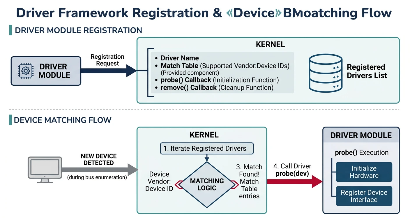
A driver framework is the glue between discovered hardware and the rest of the OS. It defines how drivers register themselves, how they're matched to devices, and how they export functionality.

╔═════════════════════════════════════════════════════════════════════════════╗
                        DRIVER MATCHING FLOW                                 
╠═════════════════════════════════════════════════════════════════════════════╣
                                                                             
  ┌─────────────┐           ┌─────────────┐           ┌─────────────┐       
   PCI Scan                Driver Reg              Matching           
  │ Finds       │            Drivers                 For each           
  │ devices     ├──────────►│ declare     ├──────────►│ device:            
  │             │            supported               call probe         
  │ ┌─────────┐ │            devices                                    
  │ │NVMe SSD│ │           │ ┌─────────┐ │                               
  │ │01:08:02│─┼───────────┼─│nvme_drv│─┼───────────┤ Returns 1          
  │ └─────────┘ │           │ └─────────┘ │                  
  │ ┌─────────┐ │           │ ┌─────────┐ │                  
  │ │AHCI Ctl│ │           │ │ahci_drv│ │             attach()         
  │ │00:1f:02│ │           │ └─────────┘ │                               
  │ └─────────┘ │           │             │                               
  └─────────────┘           └─────────────┘           └─────────────┘       
                                                                             
╚═════════════════════════════════════════════════════════════════════════════╝

Driver Interface

Define a common interface that all drivers implement:

/* PCI Device ID for matching */
typedef struct pci_device_id {
    uint16_t vendor;
    uint16_t device;
    uint8_t  class_code;
    uint8_t  subclass;
    uint8_t  prog_if;
    uint32_t driver_data;  // Private data for driver
} pci_device_id_t;

/* Match any value */
#define PCI_ANY 0xFFFF

/* Driver Interface */
typedef struct driver {
    const char* name;
    const pci_device_id_t* id_table;    // Supported devices
    int (*probe)(pci_device_t* dev);     // Check if driver supports device
    int (*attach)(pci_device_t* dev);    // Initialize device
    int (*detach)(pci_device_t* dev);    // Cleanup
    struct driver* next;
} driver_t;

driver_t* drivers = NULL;

/* Register a driver */
void driver_register(driver_t* drv) {
    drv->next = drivers;
    drivers = drv;
    kprintf("Driver registered: %s\n", drv->name);
}

/* Check if driver matches device using ID table */
static bool driver_match_id(driver_t* drv, pci_device_t* dev) {
    for (const pci_device_id_t* id = drv->id_table; id->vendor; id++) {
        if ((id->vendor == PCI_ANY || id->vendor == dev->vendor_id) &&
            (id->device == PCI_ANY || id->device == dev->device_id) &&
            (id->class_code == 0xFF || id->class_code == dev->class_code) &&
            (id->subclass == 0xFF || id->subclass == dev->subclass)) {
            return true;
        }
    }
    return false;
}

/* Match drivers to devices */
void driver_match_all(void) {
    for (pci_device_t* dev = pci_devices; dev; dev = dev->next) {
        for (driver_t* drv = drivers; drv; drv = drv->next) {
            // First check ID table, then call probe
            if (driver_match_id(drv, dev) && drv->probe(dev)) {
                if (drv->attach(dev) == 0) {
                    kprintf("Driver '%s' attached to %02x:%02x.%x\n",
                            drv->name, dev->bus, dev->slot, dev->func);
                    break;  // Device claimed
                }
            }
        }
    }
}

Here's how a driver declares its supported devices:

/* NVMe Driver Example */

/* Devices this driver supports */
static const pci_device_id_t nvme_ids[] = {
    { .vendor = PCI_ANY, .device = PCI_ANY, 
      .class_code = 0x01, .subclass = 0x08 },  // Any NVMe controller
    { .vendor = 0x8086, .device = 0xF1A5 },    // Intel Optane
    { .vendor = 0x144D, .device = 0xA808 },    // Samsung PM981
    {}  // Terminator
};

int nvme_probe(pci_device_t* dev) {
    // Additional checks if needed
    return dev->class_code == 0x01 && dev->subclass == 0x08;
}

int nvme_attach(pci_device_t* dev) {
    // Initialize NVMe controller
    kprintf("NVMe: Initializing %04x:%04x\n", dev->vendor_id, dev->device_id);
    
    // Enable bus mastering
    pci_enable_device(dev->bus, dev->slot, dev->func);
    
    // Map BAR0 (controller registers)
    uint64_t bar_base, bar_size;
    bool is_io;
    pci_decode_bar(dev->bus, dev->slot, dev->func, 0, 
                   &bar_base, &bar_size, &is_io);
    
    // Initialize controller...
    return 0;
}

int nvme_detach(pci_device_t* dev) {
    // Cleanup
    return 0;
}

static driver_t nvme_driver = {
    .name = "nvme",
    .id_table = nvme_ids,
    .probe = nvme_probe,
    .attach = nvme_attach,
    .detach = nvme_detach
};

/* Called during OS init */
void nvme_driver_init(void) {
    driver_register(&nvme_driver);
}

Device Tree

A device tree tracks the hierarchy of all discovered devices. This is useful for power management, display in lspci-like tools, and hot-plug handling:

╔═════════════════════════════════════════════════════════════════════════════╗
                         DEVICE TREE STRUCTURE                               
╠═════════════════════════════════════════════════════════════════════════════╣
                                                                             
  root                                                                      
   ├── pci0000:00 (Root Complex)                                            
   │   ├── 00:00.0 Host Bridge [8086:9A14]                                  
   │   ├── 00:02.0 VGA Controller [8086:9A49] ← Intel UHD                  
   │   ├── 00:14.0 USB Controller [8086:A0ED] ← xHCI                       
   │   ├── 00:17.0 SATA Controller [8086:A0D3] ← AHCI                      
   │   ├── 00:1c.0 PCI Bridge                                               
   │   │   └── 01:00.0 NVMe SSD [144D:A808] ← Samsung                     
   │   └── 00:1f.0 ISA Bridge                                               
   └── acpi                                                                  
       ├── HPET                                                              
       └── APIC                                                              
                                                                             
╚═════════════════════════════════════════════════════════════════════════════╝
/* Generic device node */
typedef struct device {
    char name[32];
    struct device* parent;
    struct device* children;
    struct device* sibling;
    driver_t* driver;
    void* driver_data;          // Driver-specific state
    
    enum { DEV_PCI, DEV_USB, DEV_ACPI } bus_type;
    union {
        pci_device_t* pci;
        // usb_device_t* usb;
    } bus_data;
} device_t;

device_t* device_root = NULL;

/* Add device to tree */
void device_add(device_t* dev, device_t* parent) {
    dev->parent = parent;
    dev->sibling = parent->children;
    parent->children = dev;
}

/* Print device tree (recursive) */
void device_tree_print(device_t* dev, int depth) {
    for (int i = 0; i < depth; i++) kprintf("  ");
    kprintf("├── %s", dev->name);
    if (dev->driver) kprintf(" [%s]", dev->driver->name);
    kprintf("\n");
    
    for (device_t* child = dev->children; child; child = child->sibling) {
        device_tree_print(child, depth + 1);
    }
}

/* Find device by path (e.g., "pci0000:00/00:1c.0/01:00.0") */
device_t* device_find(const char* path) {
    // Parse path and walk tree
    device_t* current = device_root;
    // ... implementation
    return current;
}
Real-World Pattern: Linux's /sys/devices/ exposes the device tree to userspace. Your shell can implement lspci and lsusb by walking this tree!

AHCI Storage

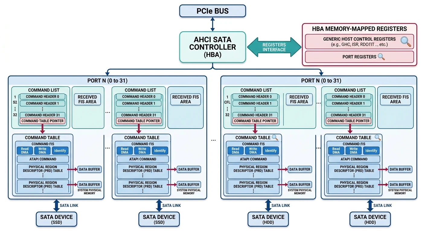
AHCI (Advanced Host Controller Interface) is the standard interface for SATA devices—hard drives and older SSDs. It's more complex than legacy IDE but supports NCQ (Native Command Queuing) for better performance.

╔═════════════════════════════════════════════════════════════════════════════╗
                         AHCI ARCHITECTURE                                   
╠═════════════════════════════════════════════════════════════════════════════╣
                                                                             
  ┌─────────────────────────────────────────────────────────────────────┐   
                       AHCI Controller (HBA)                               
    ┌─────────────────────────────────────────────────────────────┐      
                        Generic Host Control                           
      CAP | GHC | PI | IS | Version                                    
    └─────────────────────────────────────────────────────────────┘      
                                                                          
    ┌──────────┐ ┌──────────┐ ┌──────────┐ ┌──────────┐                 
    │  Port 0  │ │  Port 1  │ │  Port 2  │ │  Port 3  │  ... up to 32     
      PxCLB   │ │  PxCLB   │ │  PxCLB   │ │  PxCLB                    
      PxFB    │ │  PxFB    │ │  PxFB    │ │  PxFB                     
      PxIS    │ │  PxIS    │ │  PxIS    │ │  PxIS                     
      PxCMD   │ │  PxCMD   │ │  PxCMD   │ │  PxCMD                    
    └────┬─────┘ └────┬─────┘ └────┬─────┘ └────┬─────┘                 
          │           │           │           │                         
  └────────┼───────────┼───────────┼───────────┼──────────────────────┘   
           │           │           │           │                          
    ┌──────┴──────┐ ┌───────┴─────┐(no device)                   
       SATA HD   │ │  SATA SSD  
       1TB HDD   │ │  256GB SSD 
    └─────────────┘ └─────────────┘
                                                                             
╚═════════════════════════════════════════════════════════════════════════════╝

Initialization

AHCI initialization follows a specific sequence:

/* AHCI Memory-Mapped Registers */
typedef volatile struct {
    // Generic Host Control (offset 0x00)
    uint32_t cap;       // Host capabilities
    uint32_t ghc;       // Global host control
    uint32_t is;        // Interrupt status
    uint32_t pi;        // Ports implemented
    uint32_t vs;        // Version
    uint32_t ccc_ctl;   // Command completion coalescing control
    uint32_t ccc_ports; // CCC ports
    uint32_t em_loc;    // Enclosure management location
    uint32_t em_ctl;    // Enclosure management control
    uint32_t cap2;      // Extended capabilities
    uint32_t bohc;      // BIOS/OS handoff control
    uint8_t  rsv[0xA0 - 0x2C];
    uint8_t  vendor[0x100 - 0xA0];
    // Port registers at offset 0x100+
} ahci_hba_t;

/* Per-Port Registers (one set per port) */
typedef volatile struct {
    uint32_t clb;       // Command list base (low)
    uint32_t clbu;      // Command list base (high)
    uint32_t fb;        // FIS base (low)
    uint32_t fbu;       // FIS base (high)
    uint32_t is;        // Interrupt status
    uint32_t ie;        // Interrupt enable
    uint32_t cmd;       // Command and status
    uint32_t rsv0;
    uint32_t tfd;       // Task file data
    uint32_t sig;       // Signature
    uint32_t ssts;      // SATA status
    uint32_t sctl;      // SATA control
    uint32_t serr;      // SATA error
    uint32_t sact;      // SATA active
    uint32_t ci;        // Command issue
    uint32_t sntf;      // SATA notification
    uint32_t fbs;       // FIS-based switching
    uint32_t rsv1[11];
    uint32_t vendor[4];
} ahci_port_t;

/* Get port registers */
#define AHCI_PORT(hba, n) ((ahci_port_t*)((uint8_t*)(hba) + 0x100 + (n) * 0x80))

/* Initialize AHCI controller */
int ahci_init(pci_device_t* pci_dev) {
    // Map BAR5 (ABAR - AHCI BAR)
    uint64_t abar_base, abar_size;
    bool is_io;
    pci_decode_bar(pci_dev->bus, pci_dev->slot, pci_dev->func, 
                   5, &abar_base, &abar_size, &is_io);
    
    ahci_hba_t* hba = (ahci_hba_t*)vmap(abar_base, abar_size);
    
    // Enable AHCI mode and interrupts
    hba->ghc |= (1 << 31);  // AE (AHCI Enable)
    hba->ghc |= (1 << 1);   // IE (Interrupt Enable)
    
    // Scan ports
    uint32_t pi = hba->pi;
    for (int i = 0; i < 32; i++) {
        if (!(pi & (1 << i))) continue;  // Port not implemented
        
        ahci_port_t* port = AHCI_PORT(hba, i);
        
        // Check if device connected
        uint32_t ssts = port->ssts;
        uint8_t det = ssts & 0x0F;       // Device detection
        uint8_t ipm = (ssts >> 8) & 0x0F; // Interface power management
        
        if (det != 3 || ipm != 1) continue;  // No device or not active
        
        // Check signature
        uint32_t sig = port->sig;
        if (sig == 0x00000101) {
            kprintf("AHCI port %d: SATA HDD/SSD\n", i);
            ahci_port_init(hba, i);
        } else if (sig == 0xEB140101) {
            kprintf("AHCI port %d: ATAPI device\n", i);
        }
    }
    
    return 0;
}

Command Structure

AHCI uses a Command List and Received FIS structure per port. Each command slot points to a Command Table with the actual command and data:

╔═════════════════════════════════════════════════════════════════════════════╗
                      AHCI COMMAND STRUCTURES                                
╠═════════════════════════════════════════════════════════════════════════════╣
                                                                             
  Port Registers              Command List (1KB)          Command Table   
  ┌────────────┐               ┌─────────────────┐        ┌──────────────┐
     PxCLB    ├───────────────►│  Slot 0 (32B)  ├───────►│ CFIS (64B)   
   Cmd List                  ├─────────────────┤        ├──────────────┤
   Base Addr                   Slot 1 (32B)           ACMD (16B)   
  ├────────────┤               ├─────────────────┤        ├──────────────┤
      PxFB    ├───────┐             ...                 Reserved    
    FIS Base  ├─────────────────┤        ├──────────────┤
    Address     Slot 31(32B)          PRDT Entry 0 
  ├────────────┤└─────────────────┘        ├──────────────┤
      PxCI     PRDT Entry 1 
   Cmd Issue  Received FIS (256B)      ├──────────────┤
  └────────────┘┌─────────────────┐             ...      
  DMA Setup FIS          ├──────────────┤
                        └──────►│  PIO Setup FIS           PRDT Entry N 
                                  D2H Reg FIS            └──────────────┘
                                └─────────────────┘                          
                                                                             
╚═════════════════════════════════════════════════════════════════════════════╝
/* Command Header (32 bytes per slot, 32 slots) */
typedef struct {
    uint16_t flags;     // CFL (command FIS length), ATAPI, Write, Prefetch
    uint16_t prdtl;     // PRDT length (entries)
    uint32_t prdbc;     // PRD byte count (transferred)
    uint32_t ctba;      // Command table base (low)
    uint32_t ctbau;     // Command table base (high)
    uint32_t rsv[4];
} __attribute__((packed)) ahci_cmd_header_t;

/* Physical Region Descriptor Table Entry (16 bytes) */
typedef struct {
    uint32_t dba;       // Data base address (low)
    uint32_t dbau;      // Data base address (high)
    uint32_t rsv;
    uint32_t dbc;       // Byte count (bit 31 = interrupt on completion)
} __attribute__((packed)) ahci_prdt_entry_t;

/* Command Table (variable size: 128 bytes + N * 16 bytes for PRDTs) */
typedef struct {
    uint8_t cfis[64];   // Command FIS (Host to Device Register FIS)
    uint8_t acmd[16];   // ATAPI command (if ATAPI bit set)
    uint8_t rsv[48];
    ahci_prdt_entry_t prdt[1];  // Flexible array
} __attribute__((packed)) ahci_cmd_table_t;

/* Read sectors using AHCI */
int ahci_read(ahci_hba_t* hba, int port, uint64_t lba, 
              uint16_t count, void* buffer) {
    ahci_port_t* p = AHCI_PORT(hba, port);
    
    // Wait for port ready
    while (p->tfd & 0x88);  // BSY or DRQ set
    
    // Find free command slot
    int slot = ahci_find_slot(hba, port);
    if (slot == -1) return -1;
    
    // Get command header
    ahci_cmd_header_t* hdr = &cmd_list[port][slot];
    hdr->flags = 5;         // FIS length = 5 DWORDs (20 bytes)
    hdr->flags &= ~0x40;    // Clear Write bit (this is a read)
    hdr->prdtl = 1;         // 1 PRDT entry
    
    // Set up command table
    ahci_cmd_table_t* tbl = cmd_tables[port][slot];
    memset(tbl, 0, sizeof(ahci_cmd_table_t));
    
    // Build H2D Register FIS
    tbl->cfis[0] = 0x27;    // FIS type: H2D
    tbl->cfis[1] = 0x80;    // Command (not control)
    tbl->cfis[2] = 0x25;    // ATA_CMD_READ_DMA_EXT
    
    // LBA (48-bit)
    tbl->cfis[4] = (lba >> 0) & 0xFF;   // LBA low
    tbl->cfis[5] = (lba >> 8) & 0xFF;   // LBA mid
    tbl->cfis[6] = (lba >> 16) & 0xFF;  // LBA high
    tbl->cfis[7] = 0x40;                // Device: LBA mode
    tbl->cfis[8] = (lba >> 24) & 0xFF;  // LBA low exp
    tbl->cfis[9] = (lba >> 32) & 0xFF;  // LBA mid exp
    tbl->cfis[10] = (lba >> 40) & 0xFF; // LBA high exp
    tbl->cfis[12] = count & 0xFF;       // Sector count low
    tbl->cfis[13] = (count >> 8) & 0xFF; // Sector count high
    
    // Set up PRDT entry
    tbl->prdt[0].dba = (uint32_t)(uintptr_t)buffer;
    tbl->prdt[0].dbau = (uint32_t)((uintptr_t)buffer >> 32);
    tbl->prdt[0].dbc = (count * 512) - 1;  // 0-based
    tbl->prdt[0].dbc |= (1 << 31);         // Interrupt on completion
    
    // Issue command
    p->ci = (1 << slot);
    
    // Wait for completion
    while (p->ci & (1 << slot)) {
        if (p->is & (1 << 30)) {  // Task file error
            return -1;
        }
    }
    
    return 0;
}
NCQ (Native Command Queuing): AHCI supports up to 32 outstanding commands per port. This enables the drive to reorder operations for optimal head movement (HDDs) or parallelism (SSDs).

NVMe Storage

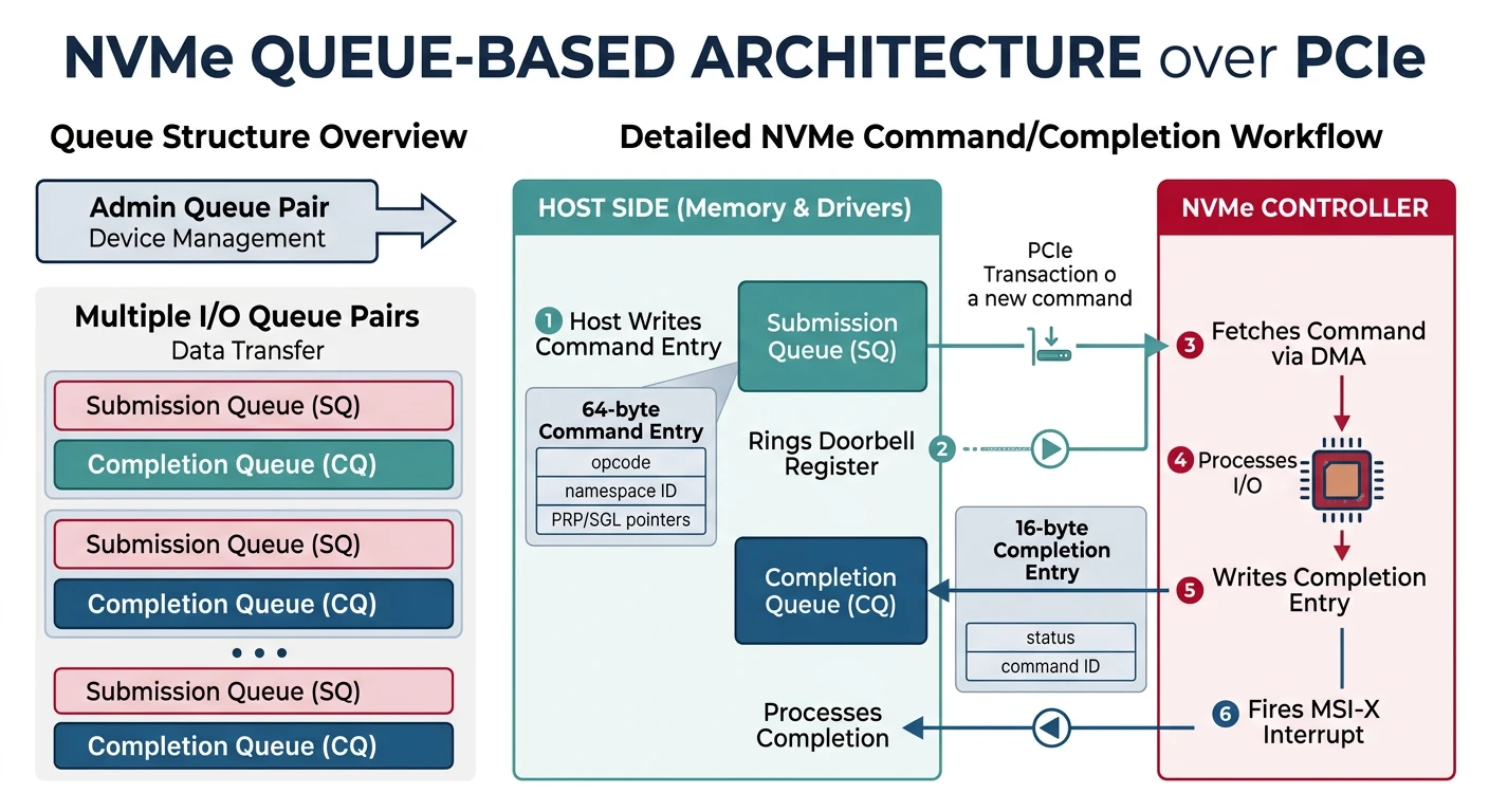
NVMe (Non-Volatile Memory Express) is the modern interface for SSDs, designed from scratch for flash storage over PCIe. Unlike AHCI (which was designed for spinning disks), NVMe uses multiple parallel queues to achieve incredible performance—millions of IOPS!

╔═════════════════════════════════════════════════════════════════════════════╗
                         NVMe ARCHITECTURE                                   
╠═════════════════════════════════════════════════════════════════════════════╣
                                                                             
  ┌──────────────────────────────────────────────────────────────────────┐  
                            CPU / Driver                                 
                                                                          
      Admin Queue                    I/O Queues (up to 65535)            
     ┌────┬────┐              ┌────┬────┐ ┌────┬────┐ ┌────┬────┐      
  ASQACQ │              │SQ1CQ1 │ │SQ2CQ2 │ │SQ3CQ3  
     └──┬─┴──┬─┘              └──┬─┴──┬─┘ └──┬─┴──┬─┘ └──┬─┴──┬─┘      
  └─────┼────┼──────────────────┼────┼──────┼────┼──────┼────┼───────┘  
        │    ▲                  │    ▲      │    ▲      │    ▲          
        ▼    │                  ▼    │      ▼    │      ▼    │          
  ┌──────────────────────────────────────────────────────────────────────┐  
                        NVMe Controller (PCIe)                           
    ┌─────────────┐  ┌─────────────┐  ┌─────────────┐                    
  Doorbell 0  │  │ Doorbell 1  │  │ Doorbell N(ring to submit)   
    └─────────────┘  └─────────────┘  └─────────────┘                    
    
                      ┌─────┴─────┐                                      
  Flash Memory  
                      │   (NAND)   │                                      
                      └───────────┘                                      
  └──────────────────────────────────────────────────────────────────────┘  
                                                                             
  SQ = Submission Queue (driver writes commands)                             
  CQ = Completion Queue (controller writes results)                          
                                                                             
╚═════════════════════════════════════════════════════════════════════════════╝

Submission/Completion Queues

NVMe's key innovation is the queue-based command interface. Instead of one command at a time (like IDE), or 32 commands (like AHCI), NVMe supports up to 65,535 I/O queue pairs, each with up to 65,536 entries!

Why So Many Queues? Modern SSDs have massive internal parallelism (hundreds of flash chips). Multiple queues let the OS feed commands from different CPU cores simultaneously, fully saturating the SSD's bandwidth.

Each queue pair consists of:

  • Submission Queue (SQ) - Driver writes 64-byte command entries
  • Completion Queue (CQ) - Controller writes 16-byte completion entries
  • Doorbell Register - Driver rings to notify controller of new commands
/* NVMe Submission Queue Entry (64 bytes) */
typedef struct {
    uint8_t  opcode;
    uint8_t  flags;
    uint16_t cid;           // Command ID
    uint32_t nsid;          // Namespace ID
    uint64_t reserved;
    uint64_t mptr;          // Metadata pointer
    uint64_t prp1;          // Physical Region Page 1
    uint64_t prp2;          // Physical Region Page 2
    uint32_t cdw10;         // Command-specific
    uint32_t cdw11;
    uint32_t cdw12;
    uint32_t cdw13;
    uint32_t cdw14;
    uint32_t cdw15;
} __attribute__((packed)) nvme_sqe_t;

/* NVMe Completion Queue Entry */
typedef struct {
    uint32_t result;        // Command-specific result
    uint32_t reserved;
    uint16_t sq_head;       // Submission queue head pointer
    uint16_t sq_id;         // Submission queue ID
    uint16_t cid;           // Command ID
    uint16_t status;        // Status field
} __attribute__((packed)) nvme_cqe_t;

The phase bit in the completion entry is clever: it flips between 0 and 1 each time the queue wraps. This lets the driver detect new completions without needing explicit notifications for each one.

NVMe Commands

NVMe commands are classified into two types:

Type Queue Examples
Admin Admin SQ/CQ Create I/O Queue, Identify, Get Log Page, Set Features
I/O I/O SQ/CQ pairs Read, Write, Flush, Dataset Management (TRIM)

Before issuing I/O commands, you must use Admin commands to identify the controller and create I/O queues:

/* NVMe Controller Initialization */
int nvme_init(pci_device_t* pci_dev) {
    // Get BAR0 (NVMe registers)
    uint64_t bar0, bar0_size;
    bool is_io;
    pci_decode_bar(pci_dev->bus, pci_dev->slot, pci_dev->func, 
                   0, &bar0, &bar0_size, &is_io);
    
    nvme_regs_t* regs = (nvme_regs_t*)map_physical(bar0, bar0_size);
    
    // Disable controller
    regs->cc &= ~1;  // Clear EN bit
    while (regs->csts & 1);  // Wait for RDY=0
    
    // Configure Admin Queue (AQ)
    regs->aqa = (ADMIN_QUEUE_SIZE - 1) | ((ADMIN_QUEUE_SIZE - 1) << 16);
    regs->asq = virt_to_phys(admin_sq);  // Submission queue
    regs->acq = virt_to_phys(admin_cq);  // Completion queue
    
    // Enable controller
    regs->cc = (0 << 20) |   // I/O CQ entry size = 16 bytes (2^4)
               (0 << 16) |   // I/O SQ entry size = 64 bytes (2^6)
               (0 << 14) |   // Shutdown notification = none
               (0 << 11) |   // Arbitration = round robin
               (6 << 7)  |   // Memory page size = 4KB (2^12)
               (0 << 4)  |   // NVM command set
               1;            // Enable
    while (!(regs->csts & 1));  // Wait for RDY=1
    
    // Issue Identify Controller command
    nvme_identify(ctrl, 0, 1, &ctrl_info);
    
    // Create I/O Completion Queue (Admin cmd 0x05)
    nvme_create_cq(ctrl, 1, IO_QUEUE_SIZE, io_cq);
    
    // Create I/O Submission Queue (Admin cmd 0x01)
    nvme_create_sq(ctrl, 1, IO_QUEUE_SIZE, io_sq, 1);
    
    return 0;
}

Now we can issue read/write commands:

/* NVMe Read Command */
int nvme_read(nvme_ctrl_t* ctrl, uint32_t nsid, 
              uint64_t lba, uint32_t blocks, void* buffer) {
    nvme_sqe_t cmd = {0};
    
    cmd.opcode = 0x02;  // Read
    cmd.cid = alloc_command_id();
    cmd.nsid = nsid;
    cmd.prp1 = virt_to_phys(buffer);
    cmd.cdw10 = lba & 0xFFFFFFFF;
    cmd.cdw11 = lba >> 32;
    cmd.cdw12 = blocks - 1;  // Zero-based count
    
    // Submit to I/O queue
    submit_command(ctrl, &cmd);
    
    // Wait for completion
    return wait_completion(ctrl, cmd.cid);
}
NVMe vs AHCI Performance: While AHCI supports 32 commands with one queue, NVMe can handle 65K commands across 65K queues. This translates to 500K+ IOPS vs AHCI's ~100K IOPS on the same SSD!

What You Can Build

Phase 15 Project: A hardware-aware OS! Your system now discovers PCI devices automatically, has a pluggable driver framework, and can access modern NVMe SSDs at full speed.

Let's combine everything into a complete storage subsystem demo:

/* storage_demo.c - Complete Storage Subsystem */
#include "pci.h"
#include "ahci.h"
#include "nvme.h"
#include "block.h"

/* Generic Block Device Interface */
typedef struct block_device {
    char name[32];
    uint64_t total_sectors;
    uint32_t sector_size;
    
    int (*read)(struct block_device* dev, uint64_t lba, 
                uint32_t count, void* buffer);
    int (*write)(struct block_device* dev, uint64_t lba,
                 uint32_t count, const void* buffer);
    void* private;  // Driver-specific data
} block_device_t;

static block_device_t devices[MAX_BLOCK_DEVICES];
static int num_devices = 0;

/* Register a block device */
void block_register(block_device_t* dev) {
    if (num_devices < MAX_BLOCK_DEVICES) {
        devices[num_devices++] = *dev;
        kprintf("Block: Registered %s (%llu MB)\n", 
                dev->name, 
                (dev->total_sectors * dev->sector_size) / (1024*1024));
    }
}

/* Storage subsystem initialization */
void storage_init(void) {
    kprintf("Storage: Scanning for devices...\n");
    
    // Scan PCI bus for storage controllers
    pci_device_t* dev;
    while ((dev = pci_next_device()) != NULL) {
        // Check class code
        if (dev->class_code != 0x01) continue;  // Mass Storage
        
        switch (dev->subclass) {
            case 0x06:  // AHCI (SATA)
                if (dev->prog_if == 0x01) {
                    kprintf("Storage: Found AHCI controller at %02x:%02x.%x\n",
                            dev->bus, dev->slot, dev->func);
                    ahci_init(dev);
                }
                break;
                
            case 0x08:  // NVMe
                if (dev->prog_if == 0x02) {
                    kprintf("Storage: Found NVMe controller at %02x:%02x.%x\n",
                            dev->bus, dev->slot, dev->func);
                    nvme_init(dev);
                }
                break;
                
            case 0x01:  // IDE (legacy)
                kprintf("Storage: Found IDE controller (legacy)\n");
                // ide_init(dev);
                break;
        }
    }
    
    kprintf("Storage: Found %d block device(s)\n", num_devices);
}

/* Read from any block device */
int block_read(int device_id, uint64_t lba, uint32_t count, void* buffer) {
    if (device_id >= num_devices) return -1;
    return devices[device_id].read(&devices[device_id], lba, count, buffer);
}

/* Demo: Read first sector of each device */
void storage_demo(void) {
    uint8_t sector[512];
    
    for (int i = 0; i < num_devices; i++) {
        kprintf("\nReading sector 0 from %s:\n", devices[i].name);
        
        if (block_read(i, 0, 1, sector) == 0) {
            // Check for MBR signature
            if (sector[510] == 0x55 && sector[511] == 0xAA) {
                kprintf("  Found MBR partition table\n");
                
                // Parse partition entries
                for (int p = 0; p < 4; p++) {
                    uint8_t* entry = §or[446 + p * 16];
                    uint8_t type = entry[4];
                    if (type != 0) {
                        uint32_t start = *(uint32_t*)&entry[8];
                        uint32_t size = *(uint32_t*)&entry[12];
                        kprintf("  Partition %d: type=0x%02x, start=%u, size=%u\n",
                                p, type, start, size);
                    }
                }
            } else if (memcmp(§or[512-2], "EFI PART", 8) == 0) {
                kprintf("  Found GPT partition table\n");
            } else {
                kprintf("  Unknown partition format\n");
            }
        } else {
            kprintf("  Read failed!\n");
        }
    }
}

Exercises

Exercise 1: Implement lspci

Create a command that lists all PCI devices with details:

void cmd_lspci(void) {
    // TODO: Enumerate all PCI devices
    // Print: Bus:Slot.Func VendorID:DeviceID Class Description
    // Example: 00:1f.2 8086:a102 0106 Intel AHCI Controller
    // Hint: Create a table of known vendor/device IDs
}
PCI Enumeration

Exercise 2: Block Device Cache

Add a simple block cache to reduce disk reads:

typedef struct cache_entry {
    uint64_t lba;
    uint8_t  data[512];
    bool     dirty;
    uint32_t access_count;
} cache_entry_t;

// TODO: Implement LRU cache with:
// - cache_read(device, lba) - check cache first
// - cache_write(device, lba, data) - write-back caching
// - cache_flush() - write all dirty entries
Caching Performance

Exercise 3: Hot-Plug Detection

Handle AHCI hot-plug events:

void ahci_interrupt_handler(int irq) {
    uint32_t is = hba->is;  // Global interrupt status
    
    for (int port = 0; port < 32; port++) {
        if (!(is & (1 << port))) continue;
        
        ahci_port_t* p = get_port(port);
        uint32_t pis = p->is;  // Port interrupt status
        
        // TODO: Handle these events:
        // - Device connected (PRCS bit)
        // - Device disconnected  
        // - Command completion
        // - Error conditions
        
        p->is = pis;  // Clear handled interrupts
    }
    
    hba->is = is;  // Clear global status
}
Hot-Plug Interrupts

Exercise 4: NVMe Multiple Queues

Create per-CPU I/O queues for maximum parallelism:

typedef struct nvme_queue_pair {
    nvme_sqe_t* sq;       // Submission queue
    nvme_cqe_t* cq;       // Completion queue
    uint16_t    sq_tail;  // Next slot to write
    uint16_t    cq_head;  // Next slot to read
    uint8_t     cq_phase; // Expected phase bit
    spinlock_t  lock;
} nvme_queue_pair_t;

// TODO: Create one queue pair per CPU
// - nvme_init_percpu_queues()
// - Use current CPU's queue for submissions
// - No locking needed if each CPU uses its own queue!
SMP NVMe
╔═════════════════════════════════════════════════════════════════════════════╗
                      PHASE 15 → PHASE 16 TRANSITION                         
╠═════════════════════════════════════════════════════════════════════════════╣
                                                                             
  ✓ Phase 15 Complete:                                                      
    • PCI bus enumeration and device discovery                               
    • Pluggable driver framework with ID matching                            
    • AHCI driver for SATA devices                                           
    • NVMe driver for modern SSDs                                            
    • Generic block device abstraction                                       
                                                                             
  → Phase 16 Preview: Performance & Optimization                             
    • Scheduler tuning (time slice, priority algorithms)                     
    • Block cache and buffer management                                      
    • Memory allocator optimization                                          
    • Profiling and bottleneck identification                                
                                                                             
╚═════════════════════════════════════════════════════════════════════════════╝

Concepts Covered

Concept Description
PCI Configuration Space256/4096-byte device descriptor with IDs, BARs, capabilities
BAR DecodingDetermining memory/IO base addresses and sizes
Driver MatchingVendor/Device ID tables for automatic driver selection
Device TreeHierarchical representation of hardware topology
AHCISATA interface with command lists and FIS structures
NVMe QueuesSubmission/Completion queue pairs for parallel I/O
Block DeviceGeneric interface abstracting storage hardware

Next Steps

With all major subsystems in place, it's time to optimize. In Phase 16, we'll tune the scheduler, implement caching strategies, and profile performance to make the OS fast and responsive.

Technology