We use cookies to enhance your browsing experience, serve personalized content, and analyze our traffic.
By clicking "Accept All", you consent to our use of cookies. See our
Privacy Policy
for more information.
Set up the Interrupt Descriptor Table (IDT), write Interrupt Service Routines (ISRs), program the PIC, handle CPU exceptions, and implement a system timer.
Phase 5 Goals: By the end of this phase, your kernel will respond to hardware events via interrupts instead of polling. You'll have a working timer, proper exception handling, and interrupt-driven keyboard input. Your OS will tick 100 times per second.
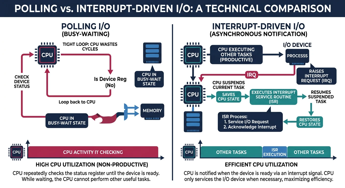
In Phase 4, we implemented keyboard input using polling—constantly checking if a key was pressed. This works but is incredibly wasteful: the CPU spins in a loop doing nothing useful while waiting. Interrupts solve this problem elegantly.
Imagine you're waiting for a pizza delivery. You could stand at the door checking every second (polling), or you could do something useful and let the doorbell notify you when it arrives (interrupts). Computers work the same way!
Polling vs interrupts: polling wastes CPU cycles constantly checking for events, while interrupts let the CPU do useful work and respond instantly when notified
Key Insight: Interrupts are the foundation of responsive computing. Instead of constantly checking if something happened (polling), the CPU can do useful work and get notified instantly when an event occurs. This is how modern operating systems achieve multitasking.
Why Interrupts?
Without interrupts, your CPU would need to:
Constantly check the keyboard for input (wasting cycles)
Constantly check if disk operations completed
Constantly check if network packets arrived
Constantly check the timer for elapsed time
With interrupts, the CPU can execute your program and be interrupted when something happens. It's like the difference between constantly asking "are we there yet?" versus getting a notification when you arrive.
THE INTERRUPT WORKFLOW
═══════════════════════════════════════════════════════════════

1. CPU executes normal code
           │
           ▼
2. Hardware event occurs (key pressed, timer tick, etc.)
           │
           ▼
3. Device sends interrupt signal to CPU
           │
           ▼
4. CPU immediately:
   ├── Saves current state (registers, flags, return address)
   ├── Looks up handler address in IDT
   └── Jumps to interrupt handler
           │
           ▼
5. Interrupt handler runs
   ├── Handles the event (read key, increment timer, etc.)
   └── Signals "End of Interrupt" to hardware
           │
           ▼
6. CPU restores state and resumes normal code
Types of Interrupts
x86 systems have three categories of interrupts:
INTERRUPT CLASSIFICATION
═══════════════════════════════════════════════════════════════

1. EXCEPTIONS (Vectors 0-31) - Synchronous, generated by CPU
   ├── FAULTS: Can be corrected (Page Fault #14)
   │           → Handler runs, then RETRY the instruction
   ├── TRAPS: Intentional (Breakpoint #3, System Call)
   │           → Handler runs, then CONTINUE to next instruction
   └── ABORTS: Unrecoverable (Double Fault #8, Machine Check)
               → System must be halted/reset

2. HARDWARE INTERRUPTS (IRQs) - Asynchronous, from devices
   ├── IRQ 0:  Timer (PIT)         → Vector 32 (after remapping)
   ├── IRQ 1:  Keyboard            → Vector 33
   ├── IRQ 2:  Cascade (PIC2)      → Vector 34
   ├── IRQ 3:  COM2                → Vector 35
   ├── IRQ 4:  COM1                → Vector 36
   ├── IRQ 5:  LPT2 / Sound        → Vector 37
   ├── IRQ 6:  Floppy              → Vector 38
   ├── IRQ 7:  LPT1                → Vector 39
   ├── IRQ 8:  RTC                 → Vector 40
   ├── IRQ 9:  ACPI                → Vector 41
   ├── IRQ 10: Available           → Vector 42
   ├── IRQ 11: Available           → Vector 43
   ├── IRQ 12: Mouse               → Vector 44
   ├── IRQ 13: FPU                 → Vector 45
   ├── IRQ 14: Primary ATA         → Vector 46
   └── IRQ 15: Secondary ATA       → Vector 47

3. SOFTWARE INTERRUPTS - Triggered by INT instruction
   └── INT 0x80: Linux system call convention
       INT 0x21: DOS function calls (historically)
Conflict Alert! By default, the PIC maps IRQs 0-7 to vectors 8-15, which CONFLICT with CPU exception vectors! We must remap IRQs to vectors 32-47 before enabling interrupts.
Interrupt Handling Flow
flowchart TD
    DEV["Hardware Device\nRaises IRQ"] --> PIC["PIC / APIC\nInterrupt Controller"]
    PIC --> CPU["CPU\nFinishes Current Instruction"]
    CPU --> SAVE["Save Context\nPush registers to stack"]
    SAVE --> IDT["IDT Lookup\nInterrupt Descriptor Table"]
    IDT --> ISR["Invoke ISR\n(Interrupt Service Routine)"]
    ISR --> TOP["Top Half\n(Critical, fast)"]
    TOP --> BOT["Bottom Half\n(Deferred work)"]
    BOT --> EOI["Send EOI\n(End of Interrupt)"]
    EOI --> RESTORE["Restore Context\nPop registers"]
    RESTORE --> IRET["IRET\nResume execution"]
Interrupt Descriptor Table (IDT)
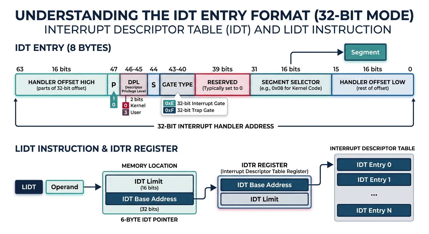
The IDT is similar to the GDT we set up in Phase 3, but instead of describing memory segments, it describes where to find interrupt handlers. Each entry tells the CPU: "When interrupt N occurs, jump to address X."
IDT entry format: each 8-byte descriptor contains the handler offset (split across two fields), segment selector, and gate type/attributes
IDT Structure
The IDT can have up to 256 entries (vectors 0-255). Each entry is 8 bytes in 32-bit protected mode:
IDT ENTRY FORMAT (32-bit Protected Mode)
═══════════════════════════════════════════════════════════════

Byte 7-6     Byte 5       Byte 4       Byte 3-2     Byte 1-0
┌────────────┬────────────┬────────────┬────────────┬────────────┐
│  Offset    │ Attributes │   Zero     │  Segment   │  Offset    │
│  31:16     │ (P,DPL,T)  │   (0x00)   │  Selector  │  15:0      │
└────────────┴────────────┴────────────┴────────────┴────────────┘

Offset: 32-bit address of the interrupt handler (split in two)
Selector: Code segment selector (usually 0x08 for kernel code)
Attributes: Present bit, privilege level, gate type

ATTRIBUTE BYTE FORMAT
┌────┬─────────┬────┬─────────────┐
│  P │   DPL   │ 0  │  Gate Type  │
└────┴─────────┴────┴─────────────┘
Bit   7    6-5    4     3-0

P = Present (1 = valid entry)
DPL = Descriptor Privilege Level (0-3)
Gate Type = 0xE (32-bit interrupt gate) or 0xF (32-bit trap gate)
The IDT supports different gate types that control interrupt behavior:
IDT GATE TYPES
═══════════════════════════════════════════════════════════════

INTERRUPT GATE (0x0E / 0x8E with Present+Ring0):
├── Automatically clears IF (Interrupt Flag) → disables interrupts
├── Used for hardware IRQs and most CPU exceptions
├── Prevents nested interrupts by default
└── You must re-enable interrupts explicitly with STI

TRAP GATE (0x0F / 0x8F with Present+Ring0):
├── Does NOT clear IF → interrupts remain enabled
├── Used for software interrupts (INT instruction)
├── Allows nested interrupts
└── Good for system calls (INT 0x80)

TASK GATE (0x05):
├── Causes a full task switch via TSS
├── Rarely used in modern OS designs
└── Can be used for Double Fault handling

What happens when an interrupt fires?
═══════════════════════════════════════════════════════════════
1. CPU pushes SS:ESP (if privilege change)
2. CPU pushes EFLAGS
3. CPU pushes CS:EIP (return address)
4. CPU pushes error code (for certain exceptions)
5. For interrupt gates: CPU clears IF (disables interrupts)
6. CPU loads new CS:EIP from IDT entry
7. Handler executes...
Interrupt vs Trap Gate: The key difference is whether interrupts are automatically disabled. For hardware IRQs, you usually want interrupt gates (auto-disable) to prevent the same interrupt from firing repeatedly while you're handling it.
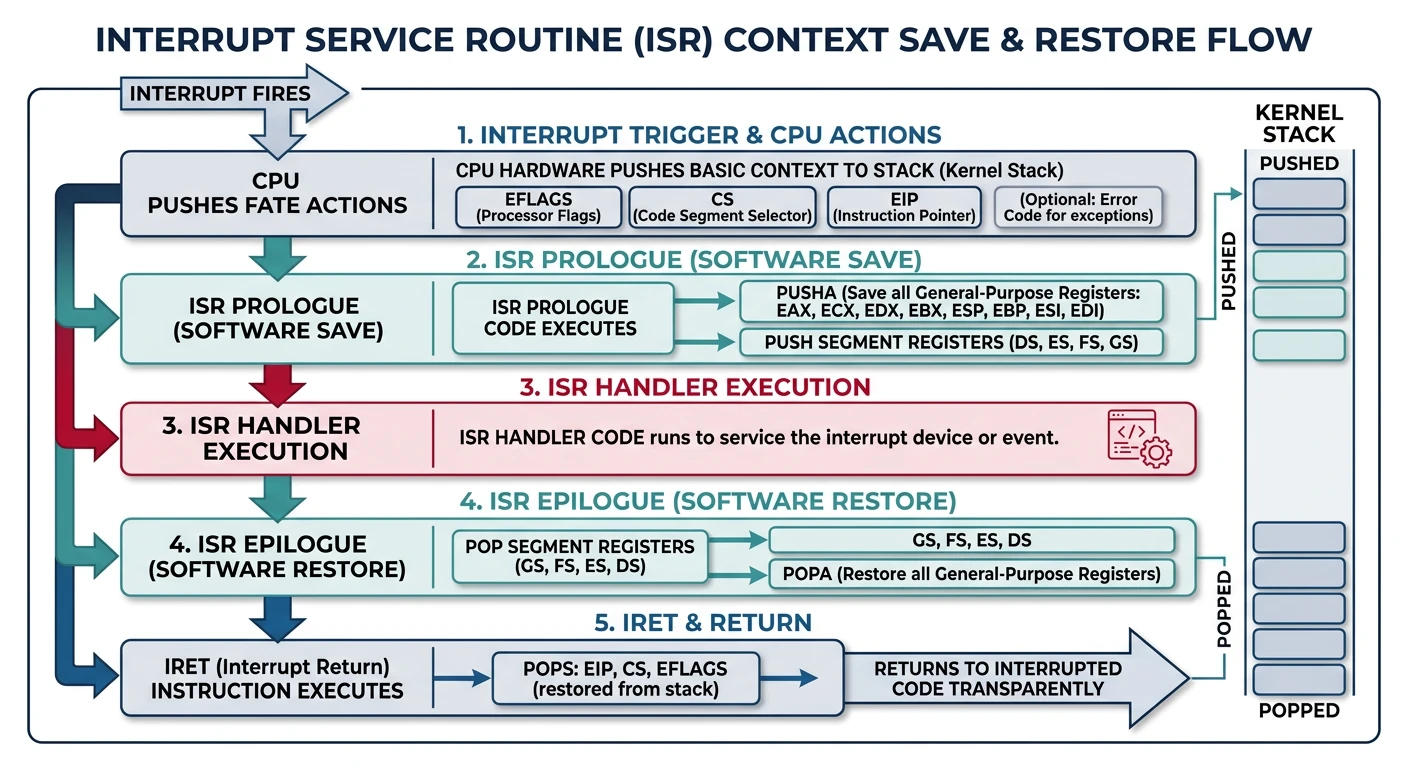
ISRs (Interrupt Service Routines) are the functions that handle interrupts. They must follow strict rules because they run in a special context—normal code was interrupted mid-execution!
ISR execution flow: save all registers (pusha), handle the interrupt, send EOI to PIC, restore registers (popa), and return via IRET
ISR Structure
Each ISR must:
Save the current CPU state (all registers)
Handle the interrupt (your actual handler code)
Restore the CPU state exactly as it was
Return using IRET instead of normal RET
STACK STATE WHEN ISR BEGINS
═══════════════════════════════════════════════════════════════

If interrupt occurred in SAME privilege level (kernel → kernel):
┌─────────────────────────┐  ← Old ESP
│      Old EFLAGS         │
├─────────────────────────┤
│      Old CS             │
├─────────────────────────┤
│      Old EIP            │  ← Return address
├─────────────────────────┤
│   Error Code (maybe)    │  ← Only for some exceptions
└─────────────────────────┘  ← ESP when ISR starts

If interrupt occurred with privilege CHANGE (user → kernel):
┌─────────────────────────┐
│      Old SS             │  ← User's stack segment
├─────────────────────────┤
│      Old ESP            │  ← User's stack pointer
├─────────────────────────┤
│      Old EFLAGS         │
├─────────────────────────┤
│      Old CS             │  ← User's code segment
├─────────────────────────┤
│      Old EIP            │
├─────────────────────────┤
│   Error Code (maybe)    │
└─────────────────────────┘  ← ESP (now pointing to kernel stack)
Context Saving
We need to save ALL registers so we can restore the interrupted code perfectly. We'll create a structure to hold this context:
/* registers.h - CPU register state structure */
#ifndef REGISTERS_H
#define REGISTERS_H

#include <stdint.h>

/* Structure pushed by our ISR stub + what CPU pushes automatically */
typedef struct {
    /* Pushed by our common stub (pusha-like) */
    uint32_t ds;                                /* Data segment */
    uint32_t edi, esi, ebp, esp_dummy;          /* General registers */
    uint32_t ebx, edx, ecx, eax;                /* (esp_dummy ignored) */

    /* Pushed by our ISR stub */
    uint32_t int_no;                            /* Interrupt number */
    uint32_t err_code;                          /* Error code (or 0) */

    /* Pushed automatically by CPU */
    uint32_t eip;                               /* Return address */
    uint32_t cs;                                /* Code segment */
    uint32_t eflags;                            /* CPU flags */

    /* Pushed by CPU only on privilege change */
    uint32_t useresp;                           /* User's ESP */
    uint32_t ss;                                /* User's SS */
} __attribute__((packed)) registers_t;

#endif
Assembly ISR Stubs
We need assembly code for the low-level ISR entry points. Each ISR pushes its number and jumps to a common stub:
; isr.asm - Interrupt Service Routine stubs
; These are the actual entry points installed in the IDT

[BITS 32]

; External C handler
extern isr_handler
extern irq_handler

; Macro for ISRs that DON'T push an error code
%macro ISR_NOERRCODE 1
    global isr%1
    isr%1:
        cli                     ; Disable interrupts
        push dword 0            ; Push dummy error code
        push dword %1           ; Push interrupt number
        jmp isr_common_stub
%endmacro

; Macro for ISRs that DO push an error code
%macro ISR_ERRCODE 1
    global isr%1
    isr%1:
        cli                     ; Disable interrupts
        ; Error code already pushed by CPU
        push dword %1           ; Push interrupt number
        jmp isr_common_stub
%endmacro

; Macro for IRQs (hardware interrupts)
%macro IRQ 2
    global irq%1
    irq%1:
        cli
        push dword 0            ; No error code for IRQs
        push dword %2           ; Push interrupt number (32+)
        jmp irq_common_stub
%endmacro

; CPU Exceptions (vectors 0-31)
ISR_NOERRCODE  0   ; #DE - Division by Zero
ISR_NOERRCODE  1   ; #DB - Debug
ISR_NOERRCODE  2   ; NMI - Non-Maskable Interrupt
ISR_NOERRCODE  3   ; #BP - Breakpoint
ISR_NOERRCODE  4   ; #OF - Overflow
ISR_NOERRCODE  5   ; #BR - Bound Range Exceeded
ISR_NOERRCODE  6   ; #UD - Invalid Opcode
ISR_NOERRCODE  7   ; #NM - No Math Coprocessor
ISR_ERRCODE    8   ; #DF - Double Fault (error code = 0 always)
ISR_NOERRCODE  9   ; Coprocessor Segment Overrun (obsolete)
ISR_ERRCODE   10   ; #TS - Invalid TSS
ISR_ERRCODE   11   ; #NP - Segment Not Present
ISR_ERRCODE   12   ; #SS - Stack Segment Fault
ISR_ERRCODE   13   ; #GP - General Protection Fault
ISR_ERRCODE   14   ; #PF - Page Fault
ISR_NOERRCODE 15   ; Reserved
ISR_NOERRCODE 16   ; #MF - x87 FPU Error
ISR_ERRCODE   17   ; #AC - Alignment Check
ISR_NOERRCODE 18   ; #MC - Machine Check
ISR_NOERRCODE 19   ; #XM - SIMD Exception
; 20-31 reserved...

; Hardware IRQs (mapped to vectors 32-47)
IRQ  0, 32  ; Timer (PIT)
IRQ  1, 33  ; Keyboard
IRQ  2, 34  ; Cascade for slave PIC
IRQ  3, 35  ; COM2
IRQ  4, 36  ; COM1
IRQ  5, 37  ; LPT2
IRQ  6, 38  ; Floppy
IRQ  7, 39  ; LPT1 / Spurious
IRQ  8, 40  ; RTC
IRQ  9, 41  ; ACPI
IRQ 10, 42  ; Available
IRQ 11, 43  ; Available
IRQ 12, 44  ; Mouse
IRQ 13, 45  ; FPU
IRQ 14, 46  ; Primary ATA
IRQ 15, 47  ; Secondary ATA

; Common ISR stub - saves CPU state, calls C handler
isr_common_stub:
    ; Save all general-purpose registers
    pusha

    ; Save data segment
    mov ax, ds
    push eax

    ; Load kernel data segment
    mov ax, 0x10        ; Kernel data segment selector
    mov ds, ax
    mov es, ax
    mov fs, ax
    mov gs, ax

    ; Push pointer to register structure (stack pointer)
    push esp

    ; Call C handler: isr_handler(registers_t* regs)
    call isr_handler

    ; Remove pushed pointer
    add esp, 4

    ; Restore data segment
    pop eax
    mov ds, ax
    mov es, ax
    mov fs, ax
    mov gs, ax

    ; Restore general-purpose registers
    popa

    ; Clean up pushed error code and interrupt number
    add esp, 8

    ; Return from interrupt (pops EIP, CS, EFLAGS, and possibly ESP, SS)
    iret

; Common IRQ stub - similar but calls irq_handler
irq_common_stub:
    pusha

    mov ax, ds
    push eax

    mov ax, 0x10
    mov ds, ax
    mov es, ax
    mov fs, ax
    mov gs, ax

    push esp
    call irq_handler
    add esp, 4

    pop eax
    mov ds, ax
    mov es, ax
    mov fs, ax
    mov gs, ax

    popa
    add esp, 8
    iret
Error Code Complexity: Some exceptions push an error code automatically, others don't. Our macros handle this by pushing a dummy 0 when needed. The Page Fault (#14) error code contains valuable information about what went wrong!
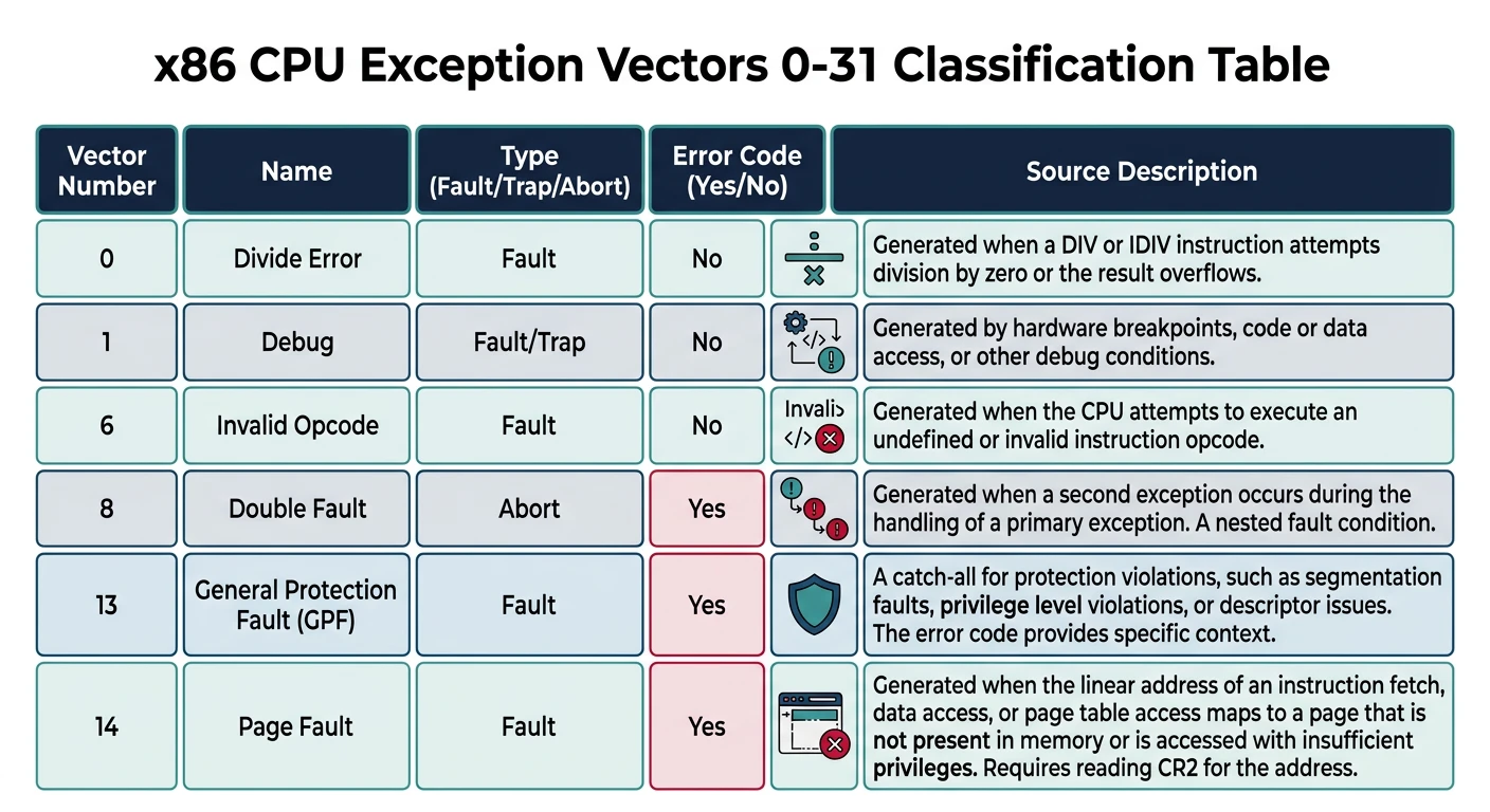
CPU Exceptions
CPU exceptions are interrupts generated by the processor itself when something goes wrong (or intentionally, like breakpoints). Handling them properly is crucial for a stable OS.
x86 CPU exceptions: vectors 0–31 are reserved for faults (restartable), traps (post-instruction), and aborts (unrecoverable) generated by the processor
Exception Types
x86 CPU EXCEPTIONS (Vectors 0-31)
═══════════════════════════════════════════════════════════════

Vec │ Name                   │ Type   │ Err? │ Description
────┼────────────────────────┼────────┼──────┼─────────────────────
 0  │ #DE Division Error     │ Fault  │  No  │ DIV/IDIV by zero
 1  │ #DB Debug              │ F/Trap │  No  │ Debug exception
 2  │ NMI                    │ Int    │  No  │ Non-Maskable Interrupt
 3  │ #BP Breakpoint         │ Trap   │  No  │ INT 3 instruction
 4  │ #OF Overflow           │ Trap   │  No  │ INTO instruction
 5  │ #BR Bound Range        │ Fault  │  No  │ BOUND instruction
 6  │ #UD Invalid Opcode     │ Fault  │  No  │ Unknown instruction
 7  │ #NM No FPU             │ Fault  │  No  │ FPU not available
 8  │ #DF Double Fault       │ Abort  │ Yes* │ Exception during exc.
 9  │ (obsolete)             │  -     │  No  │ Coprocessor overrun
10  │ #TS Invalid TSS        │ Fault  │ Yes  │ Task switch failed
11  │ #NP Segment Not Pres.  │ Fault  │ Yes  │ Segment not in memory
12  │ #SS Stack Fault        │ Fault  │ Yes  │ Stack segment issue
13  │ #GP General Protection │ Fault  │ Yes  │ Memory/privilege error
14  │ #PF Page Fault         │ Fault  │ Yes  │ Page not present/etc.
15  │ (reserved)             │  -     │  -   │ Intel reserved
16  │ #MF x87 FPU Error      │ Fault  │  No  │ Math error
17  │ #AC Alignment Check    │ Fault  │ Yes  │ Unaligned access
18  │ #MC Machine Check      │ Abort  │  No  │ Hardware error
19  │ #XM SIMD Exception     │ Fault  │  No  │ SSE/SSE2/etc. error
20-31│ (reserved)            │  -     │  -   │ Intel reserved

*Double Fault error code is always 0
The Page Fault (#14) error code is particularly useful for debugging:
PAGE FAULT ERROR CODE FORMAT
═══════════════════════════════════════════════════════════════

Bit │ Name │ Meaning when SET
────┼──────┼─────────────────────────────────────────
 0  │  P   │ Page-level protection violation (vs. not present)
 1  │ W/R  │ Write access caused fault (vs. read)
 2  │ U/S  │ User-mode access (vs. supervisor/kernel)
 3  │ RSVD │ Reserved bit set in page table
 4  │ I/D  │ Instruction fetch (vs. data access)
 5  │  PK  │ Protection key violation
 6  │  SS  │ Shadow stack access
 7  │ HLAT │ HLAT paging fault
15  │ SGX  │ SGX violation

EXAMPLE INTERPRETATIONS:
Error Code 0x00: Page not present, read, kernel
Error Code 0x02: Page not present, write, kernel
Error Code 0x04: Page not present, read, user
Error Code 0x05: Page present but protected, read, user
Error Code 0x07: Page present but protected, write, user

The faulting linear address is stored in CR2!
General Protection Fault (GPF) Causes
GPF (#13) is the "catch-all" for privilege violations. Common causes:
Writing to read-only memory
Accessing kernel memory from user mode
Loading invalid segment selectors
Executing privileged instructions from Ring 3
Exceeding segment limits
Debugging
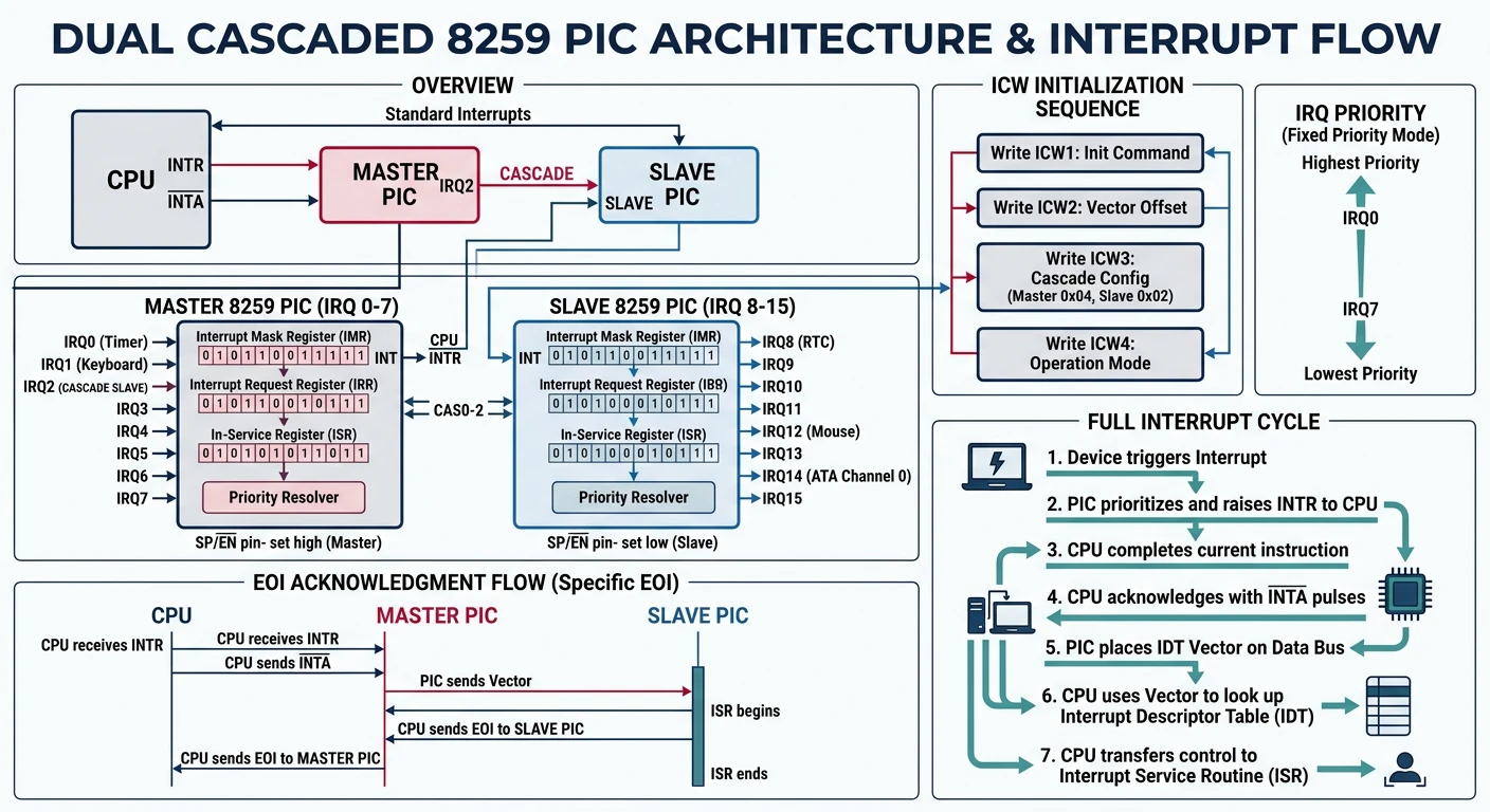
Programming the PIC
The Programmable Interrupt Controller (PIC) is a chip that manages hardware interrupts. The original IBM PC used the Intel 8259A, and modern systems emulate it for compatibility.
Dual PIC architecture: the master 8259 handles IRQ 0–7 and cascades to the slave 8259 for IRQ 8–15, delivering a single INTR signal to the CPU
Why Remap? By default, the PIC maps IRQ 0-7 to vectors 8-15, which conflicts with CPU exceptions (8 = Double Fault, 13 = GPF, 14 = Page Fault). We must remap them to vectors 32+ where there's no conflict.
IRQ Remapping
The PIC is initialized by sending a sequence of Initialization Command Words (ICWs):
After handling any IRQ, you must send an EOI command to the PIC, or it won't deliver any more interrupts of that priority:
/**
 * Send End-of-Interrupt signal to PIC
 * MUST be called at end of every IRQ handler!
 */
void pic_send_eoi(uint8_t irq) {
    /* If this came from the slave PIC, send EOI to both */
    if (irq >= 8) {
        outb(PIC2_COMMAND, PIC_EOI);
    }
    /* Always send EOI to master */
    outb(PIC1_COMMAND, PIC_EOI);
}

/**
 * Mask (disable) a specific IRQ
 */
void pic_set_mask(uint8_t irq) {
    uint16_t port;
    uint8_t value;

    if (irq < 8) {
        port = PIC1_DATA;
    } else {
        port = PIC2_DATA;
        irq -= 8;
    }
    value = inb(port) | (1 << irq);
    outb(port, value);
}

/**
 * Unmask (enable) a specific IRQ
 */
void pic_clear_mask(uint8_t irq) {
    uint16_t port;
    uint8_t value;

    if (irq < 8) {
        port = PIC1_DATA;
    } else {
        port = PIC2_DATA;
        irq -= 8;
    }
    value = inb(port) & ~(1 << irq);
    outb(port, value);
}
Critical: Forgetting EOI
If you forget to send EOI:
The PIC thinks you're still handling that interrupt
No more interrupts of that priority or lower will fire
Your timer/keyboard will appear "frozen"
For slave PIC IRQs (8-15), you must send EOI to BOTH PICs
Common Bug
Programmable Interval Timer (PIT)
The PIT (Intel 8253/8254) is a hardware timer that can generate periodic interrupts. It's essential for time-keeping, scheduling, and implementing sleep functions.
Understanding the PIT
PIT ARCHITECTURE
═══════════════════════════════════════════════════════════════

┌───────────────────────────────────────────────────────────────┐
│                    8253/8254 PIT Chip                         │
├───────────┬───────────┬───────────┬───────────────────────────┤
│           │           │           │                           │
│ Channel 0 │ Channel 1 │ Channel 2 │    Common Control         │
│           │           │           │                           │
│   IRQ 0   │   DRAM    │  PC      │    Base Frequency:        │
│  (Timer)  │  Refresh  │ Speaker   │    1,193,182 Hz           │
│           │ (Legacy)  │           │                           │
├───────────┴───────────┴───────────┤    Output = Base / Div    │
│  Port 0x40  Port 0x41  Port 0x42  │    Command Port: 0x43     │
└───────────────────────────────────┴───────────────────────────┘

WHY 1,193,182 Hz?
─────────────────────────
The original IBM PC used a 14.31818 MHz crystal (for NTSC video).
This was divided by 12 for the PIT: 14,318,180 / 12 = 1,193,182

COMMON DIVISORS:
─────────────────────────
Divisor    │ Frequency  │ Period     │ Use Case
───────────┼────────────┼────────────┼──────────────────
    1193   │ ~1000 Hz   │ ~1 ms      │ High precision
   11932   │  100 Hz    │ 10 ms      │ Typical OS tick
   47727   │  25 Hz     │ 40 ms      │ Retro gaming
  119318   │  10 Hz     │ 100 ms     │ Battery saving
Choosing a Tick Rate: 100 Hz (10ms periods) is a good balance. Higher rates give finer scheduling granularity but increase interrupt overhead. Linux defaults to 250 Hz or 1000 Hz depending on configuration.
Configuring the Timer
/* timer.c - Programmable Interval Timer driver */

#include "io.h"
#include "pic.h"
#include "registers.h"

/* PIT I/O Ports */
#define PIT_CHANNEL0    0x40    /* Channel 0 data port */
#define PIT_CHANNEL1    0x41    /* Channel 1 data port */
#define PIT_CHANNEL2    0x42    /* Channel 2 data port */
#define PIT_COMMAND     0x43    /* Mode/Command register */

/* PIT Command Register Bits */
#define PIT_SEL_CH0     0x00    /* Select channel 0 */
#define PIT_SEL_CH1     0x40    /* Select channel 1 */
#define PIT_SEL_CH2     0x80    /* Select channel 2 */
#define PIT_ACCESS_LH   0x30    /* Access: lobyte then hibyte */
#define PIT_MODE2       0x04    /* Mode 2: rate generator */
#define PIT_MODE3       0x06    /* Mode 3: square wave */
#define PIT_BINARY      0x00    /* Binary counting (vs BCD) */

/* Base frequency of the PIT */
#define PIT_BASE_FREQ   1193182

/* Our desired timer frequency */
#define TIMER_FREQ_HZ   100     /* 100 Hz = 10ms periods */

/* Global tick counter (volatile because modified in ISR) */
static volatile uint32_t timer_ticks = 0;

/**
 * Initialize the PIT for periodic interrupts
 *
 * Command byte breakdown for 0x36:
 *   Bits 7-6: 00 = Channel 0
 *   Bits 5-4: 11 = Access lobyte/hibyte
 *   Bits 3-1: 011 = Mode 3 (square wave)
 *   Bit 0:    0 = Binary counting
 */
void timer_init(uint32_t frequency) {
    /* Calculate divisor for desired frequency */
    uint32_t divisor = PIT_BASE_FREQ / frequency;

    /* Clamp divisor to 16-bit range */
    if (divisor > 0xFFFF) {
        divisor = 0xFFFF;
    }
    if (divisor < 1) {
        divisor = 1;
    }

    /* Send command byte: Channel 0, lobyte/hibyte, square wave, binary */
    outb(PIT_COMMAND, PIT_SEL_CH0 | PIT_ACCESS_LH | PIT_MODE3 | PIT_BINARY);

    /* Send divisor (low byte first, then high byte) */
    outb(PIT_CHANNEL0, (uint8_t)(divisor & 0xFF));
    outb(PIT_CHANNEL0, (uint8_t)((divisor >> 8) & 0xFF));

    /* Enable IRQ 0 */
    pic_clear_mask(0);
}

/**
 * Get current tick count
 */
uint32_t timer_get_ticks(void) {
    return timer_ticks;
}

/**
 * Sleep for a given number of ticks
 */
void timer_sleep(uint32_t ticks) {
    uint32_t end_ticks = timer_ticks + ticks;
    while (timer_ticks < end_ticks) {
        /* Wait - could use HLT for power saving */
        __asm__ volatile("hlt");
    }
}

/**
 * Get uptime in seconds
 */
uint32_t timer_uptime_seconds(void) {
    return timer_ticks / TIMER_FREQ_HZ;
}
Timer IRQ Handler
The timer handler is called every tick (e.g., 100 times per second at 100 Hz):
/**
 * Timer interrupt handler (IRQ 0 → INT 32)
 * Called from irq_handler dispatch
 */
void timer_handler(registers_t* regs) {
    timer_ticks++;

    /* Periodic tasks could go here:
     * - Update system time
     * - Check for sleeping processes to wake
     * - Trigger scheduler (preemptive multitasking)
     */

    /* Note: EOI is sent by irq_handler after this returns */
}

/**
 * Main IRQ dispatcher (called from irq_common_stub)
 */
void irq_handler(registers_t* regs) {
    /* Calculate IRQ number from interrupt number */
    uint8_t irq = regs->int_no - 32;

    /* Dispatch to specific handler */
    switch (irq) {
        case 0:  /* Timer */
            timer_handler(regs);
            break;
        case 1:  /* Keyboard */
            keyboard_handler(regs);
            break;
        /* Add more IRQ handlers here */
    }

    /* Send End-of-Interrupt to PIC */
    pic_send_eoi(irq);
}
Implementing a Simple Clock
Once you have timer interrupts working, you can display a running clock:
void display_uptime(void) {
    uint32_t total = timer_get_ticks() / 100;  /* Assuming 100 Hz */
    uint32_t hours = total / 3600;
    uint32_t minutes = (total % 3600) / 60;
    uint32_t seconds = total % 60;

    /* Display at fixed screen position */
    terminal_set_cursor(70, 0);
    kprintf("%02d:%02d:%02d", hours, minutes, seconds);
}
Exercise
Keyboard IRQ Handler
In Phase 4, we used polling to read keyboard input. Now we'll upgrade to interrupt-driven input, which is more efficient and responsive.
POLLING vs INTERRUPT-DRIVEN I/O
═══════════════════════════════════════════════════════════════

POLLING (What we did in Phase 4):
┌──────────────────────────────────────────────────────────────┐
│  while (true) {                                              │
│      if (keyboard_data_available()) {  <- Wastes CPU cycles  │
│          process_key();                   checking constantly│
│      }                                                       │
│  }                                                           │
└──────────────────────────────────────────────────────────────┘

INTERRUPT-DRIVEN (What we do now):
┌──────────────────────────────────────────────────────────────┐
│  CPU does useful work...                                     │
│  CPU does useful work...                                     │
│  [USER PRESSES KEY]                                          │
│  CPU jumps to keyboard_handler() ← Hardware notifies us!     │
│  keyboard_handler() stores key ─>│ Buffer │                  │
│  CPU resumes useful work...                                  │
└──────────────────────────────────────────────────────────────┘
Circular Buffer
We need a buffer to store keypresses until the program is ready to read them. A circular (ring) buffer is perfect:
/* keyboard.c - Interrupt-driven keyboard driver */

#include "io.h"
#include "pic.h"
#include "registers.h"

/* PS/2 Keyboard Ports */
#define KEYBOARD_DATA_PORT      0x60
#define KEYBOARD_STATUS_PORT    0x64

/* Circular buffer for keyboard input */
#define KEYBOARD_BUFFER_SIZE    256
static volatile char keyboard_buffer[KEYBOARD_BUFFER_SIZE];
static volatile uint8_t buffer_head = 0;  /* Write position */
static volatile uint8_t buffer_tail = 0;  /* Read position */

/* Modifier key states */
static volatile uint8_t shift_pressed = 0;
static volatile uint8_t ctrl_pressed = 0;
static volatile uint8_t alt_pressed = 0;

/* Scan code to ASCII lookup tables (US QWERTY) */
static const char scancode_normal[128] = {
    0,  27, '1','2','3','4','5','6','7','8','9','0','-','=','\b',
    '\t','q','w','e','r','t','y','u','i','o','p','[',']','\n',
    0,  'a','s','d','f','g','h','j','k','l',';','\'','`',
    0,  '\\','z','x','c','v','b','n','m',',','.','/', 0,  '*',
    0,  ' ', 0,   0,  0,  0,  0,  0,  0,  0,  0,  0,  0,   0,
    /* ... function keys, etc ... */
};

static const char scancode_shifted[128] = {
    0,  27, '!','@','#','$','%','^','&','*','(',')','_','+','\b',
    '\t','Q','W','E','R','T','Y','U','I','O','P','{','}','\n',
    0,  'A','S','D','F','G','H','J','K','L',':','"','~',
    0,  '|','Z','X','C','V','B','N','M','<','>','?', 0,  '*',
    0,  ' ', 0,   0,  0,  0,  0,  0,  0,  0,  0,  0,  0,   0,
};

/**
 * Add a character to the keyboard buffer
 */
static void buffer_add(char c) {
    uint8_t next = (buffer_head + 1) % KEYBOARD_BUFFER_SIZE;

    /* Only add if buffer isn't full */
    if (next != buffer_tail) {
        keyboard_buffer[buffer_head] = c;
        buffer_head = next;
    }
    /* If full, keypress is dropped (you could beep here) */
}

/**
 * Check if keyboard buffer has data
 */
int keyboard_has_data(void) {
    return buffer_head != buffer_tail;
}

/**
 * Read one character from keyboard buffer (blocking)
 */
char keyboard_getchar(void) {
    /* Wait for data */
    while (!keyboard_has_data()) {
        __asm__ volatile("hlt");  /* Sleep until next interrupt */
    }

    char c = keyboard_buffer[buffer_tail];
    buffer_tail = (buffer_tail + 1) % KEYBOARD_BUFFER_SIZE;
    return c;
}

/**
 * Keyboard interrupt handler (IRQ 1 → INT 33)
 */
void keyboard_handler(registers_t* regs) {
    /* Read the scancode */
    uint8_t scancode = inb(KEYBOARD_DATA_PORT);

    /* Check if this is a key release (bit 7 set) */
    int key_released = scancode & 0x80;
    uint8_t code = scancode & 0x7F;

    /* Handle modifier keys */
    if (code == 0x2A || code == 0x36) {         /* Left/Right Shift */
        shift_pressed = !key_released;
        return;
    }
    if (code == 0x1D) {                          /* Ctrl */
        ctrl_pressed = !key_released;
        return;
    }
    if (code == 0x38) {                          /* Alt */
        alt_pressed = !key_released;
        return;
    }

    /* Only process key presses, not releases */
    if (key_released) {
        return;
    }

    /* Look up the ASCII character */
    char c;
    if (shift_pressed) {
        c = scancode_shifted[code];
    } else {
        c = scancode_normal[code];
    }

    /* Handle Ctrl+C (break) */
    if (ctrl_pressed && (c == 'c' || c == 'C')) {
        /* Could set a flag for process termination */
        buffer_add(3);  /* ASCII ETX (Ctrl+C) */
        return;
    }

    /* Add to buffer if it's a printable character */
    if (c != 0) {
        buffer_add(c);
    }

    /* Note: EOI is sent by irq_handler after this returns */
}
Putting It All Together
Here's the complete interrupt system initialization:
/* Initialize all interrupt-related subsystems */
void interrupts_init(void) {
    /* Set up the Interrupt Descriptor Table */
    idt_init();

    /* Remap the PIC (move IRQs to vectors 32-47) */
    pic_remap();

    /* Initialize the timer at 100 Hz */
    timer_init(100);

    /* Enable the keyboard IRQ */
    pic_clear_mask(1);

    /* Enable interrupts! */
    __asm__ volatile("sti");

    kprintf("Interrupts enabled.\n");
}

/* Main kernel entry point */
void kernel_main(void) {
    /* Initialize display */
    terminal_init();
    kprintf("Kernel starting...\n");

    /* Set up interrupt handling */
    interrupts_init();

    /* Now we can use interrupt-driven I/O! */
    kprintf("Type something: ");

    while (1) {
        char c = keyboard_getchar();
        terminal_putc(c);  /* Echo the character */
    }
}
Benefits of Interrupt-Driven I/O
CPU Efficiency: No wasted cycles polling; CPU can do useful work or sleep
Responsiveness: Input is captured immediately when it happens
Buffering: Keypresses aren't lost if the program is busy
Foundation for Multitasking: Timer interrupt enables preemptive scheduling
Best Practice
What You Can Build
Phase 5 Achievement: You now have a fully interrupt-driven kernel! It ticks 100 times per second, responds instantly to keypresses, and handles CPU exceptions gracefully. This is the foundation for everything else in an operating system.
Project: Timer-Driven Status Bar
Let's put everything together with a status bar that updates in real-time:
/* status.c - Real-time status bar */

#include "terminal.h"
#include "timer.h"
#include "keyboard.h"

/* Status bar lives at row 0 */
#define STATUS_ROW  0

/* Called periodically (e.g., every 10 ticks = 100ms) */
void update_status_bar(void) {
    static uint32_t last_update = 0;
    uint32_t now = timer_get_ticks();

    /* Only update every 10 ticks (100ms at 100Hz) */
    if (now - last_update < 10) {
        return;
    }
    last_update = now;

    /* Save cursor position */
    int saved_x = terminal_getx();
    int saved_y = terminal_gety();

    /* Draw status bar with different colors */
    uint8_t saved_color = terminal_getcolor();
    terminal_set_color(vga_make_color(VGA_BLACK, VGA_LIGHT_GREY));

    /* Clear status line */
    terminal_set_cursor(0, STATUS_ROW);
    for (int i = 0; i < 80; i++) {
        terminal_putc(' ');
    }

    /* Left: OS name */
    terminal_set_cursor(1, STATUS_ROW);
    terminal_set_color(vga_make_color(VGA_LIGHT_CYAN, VGA_LIGHT_GREY));
    kprintf(" MyOS v0.5 ");

    /* Center: Current time */
    terminal_set_cursor(35, STATUS_ROW);
    terminal_set_color(vga_make_color(VGA_BLACK, VGA_LIGHT_GREY));
    uint32_t uptime = timer_uptime_seconds();
    kprintf(" %02d:%02d:%02d ",
            uptime / 3600,
            (uptime % 3600) / 60,
            uptime % 60);

    /* Right: Keyboard buffer status */
    terminal_set_cursor(65, STATUS_ROW);
    if (keyboard_has_data()) {
        terminal_set_color(vga_make_color(VGA_LIGHT_GREEN, VGA_LIGHT_GREY));
        kprintf("Data Ready");
    } else {
        terminal_set_color(vga_make_color(VGA_DARK_GREY, VGA_LIGHT_GREY));
        kprintf("  Idle    ");
    }

    /* Restore cursor and color */
    terminal_set_color(saved_color);
    terminal_set_cursor(saved_x, saved_y);
}

/* Hook into timer interrupt */
void timer_handler(registers_t* regs) {
    timer_ticks++;
    update_status_bar();
}
Exercises
Exercise 1: Implement sleep() Function
Create a user-friendly sleep function that waits for a specified number of milliseconds:
void sleep_ms(uint32_t milliseconds) {
    /* Convert ms to ticks based on TIMER_FREQ_HZ */
    /* Handle rounding: 1ms at 100Hz = 0.1 ticks, round up! */
}
Code Challenge
Exercise 2: Add IRQ Handler Registration
Instead of a big switch statement in irq_handler, implement a registration system:
Use the PC Speaker (port 0x61 + PIT Channel 2) to generate a beep:
void beep(uint32_t frequency, uint32_t duration_ms);

/* The PC Speaker is controlled by:
 * - PIT Channel 2 (0x42) for frequency
 * - Port 0x61 bits 0-1 for enabling
 */
Hardware Fun
Next Steps
Your kernel now has a heartbeat! With interrupts working, you have the foundation for:
Preemptive Multitasking: Timer interrupts let you switch between processes
Responsive I/O: Handle keyboard, mouse, disk without polling
Time Keeping: Track uptime, implement delays, schedule events
Power Efficiency: Let CPU sleep between interrupts (HLT instruction)