We use cookies to enhance your browsing experience, serve personalized content, and analyze our traffic.
By clicking "Accept All", you consent to our use of cookies. See our
Privacy Policy
for more information.
Kernel Development Series Phase 2: Real Mode - First Steps Near Hardware
February 6, 2026Wasil Zafar30 min read
Write your first bootloader in x86 real mode. Master real mode memory addressing, BIOS interrupts, boot sector structure, and interact directly with hardware without any operating system.
Phase 2 Goals: By the end of this phase, you'll have written your own bootloader that runs on bare metal, understands x86 real mode memory addressing, and can interact with hardware through BIOS interrupts.
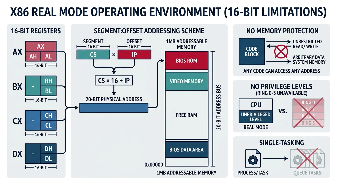
When an x86 CPU powers on, it doesn't start in 64-bit mode with gigabytes of memory. Instead, it wakes up in Real Mode - a 16-bit operating mode that dates back to the original Intel 8086 processor from 1978. This might seem like ancient history, but understanding real mode is essential because it's where every x86 computer begins.
Think of real mode as "training wheels mode" for the CPU. It's simple, direct, and gives you complete access to hardware - but with significant limitations that made sense for computers with 640KB of RAM.
Real mode: the CPU starts in 16-bit mode with direct hardware access, 1MB address space, no memory protection, and no privilege separation
Real Mode Analogy: Driving a Classic Car
Modern CPUs in protected/long mode are like modern cars with:
Power steering (memory management hardware)
Airbags (memory protection)
GPS navigation (virtual memory)
Speed limiters (privilege levels)
Real mode is like a 1970s muscle car - no safety features, but complete control. You feel every bump in the road (every hardware quirk), and a crash means real damage (no protection mechanisms).
Key Insight: Real mode is the CPU's initial state after power-on. It's a 16-bit mode with direct hardware access but limited memory (1MB) and no protection. All x86 processors start here for backward compatibility.
Even though we'll quickly move to protected mode (Phase 3), learning real mode is valuable:
Practical Reasons
BIOS services only work in real mode
Must initialize hardware before switching modes
Boot sector code runs in real mode
Many bootloaders stay in real mode initially
Educational Reasons
Simpler model - great for learning
Direct hardware access - see how things work
Understand x86 history and compatibility
Appreciate why protected mode was invented
Real Mode Limitations
Limitation
Real Mode Constraint
Modern Capabilities
Memory Access
1MB (20-bit addresses)
Terabytes (64-bit addresses)
Instruction Width
16-bit
64-bit
Memory Protection
None - any code can overwrite anything
Full isolation between processes
Multitasking Support
None - manual saving/restoring
Hardware task switching
Privilege Levels
One level - everything has full access
4 rings (Ring 0-3)
Real Mode Memory Addressing
Real mode's most distinctive feature is its segmented memory model. This is where many beginners get confused, so let's break it down completely.
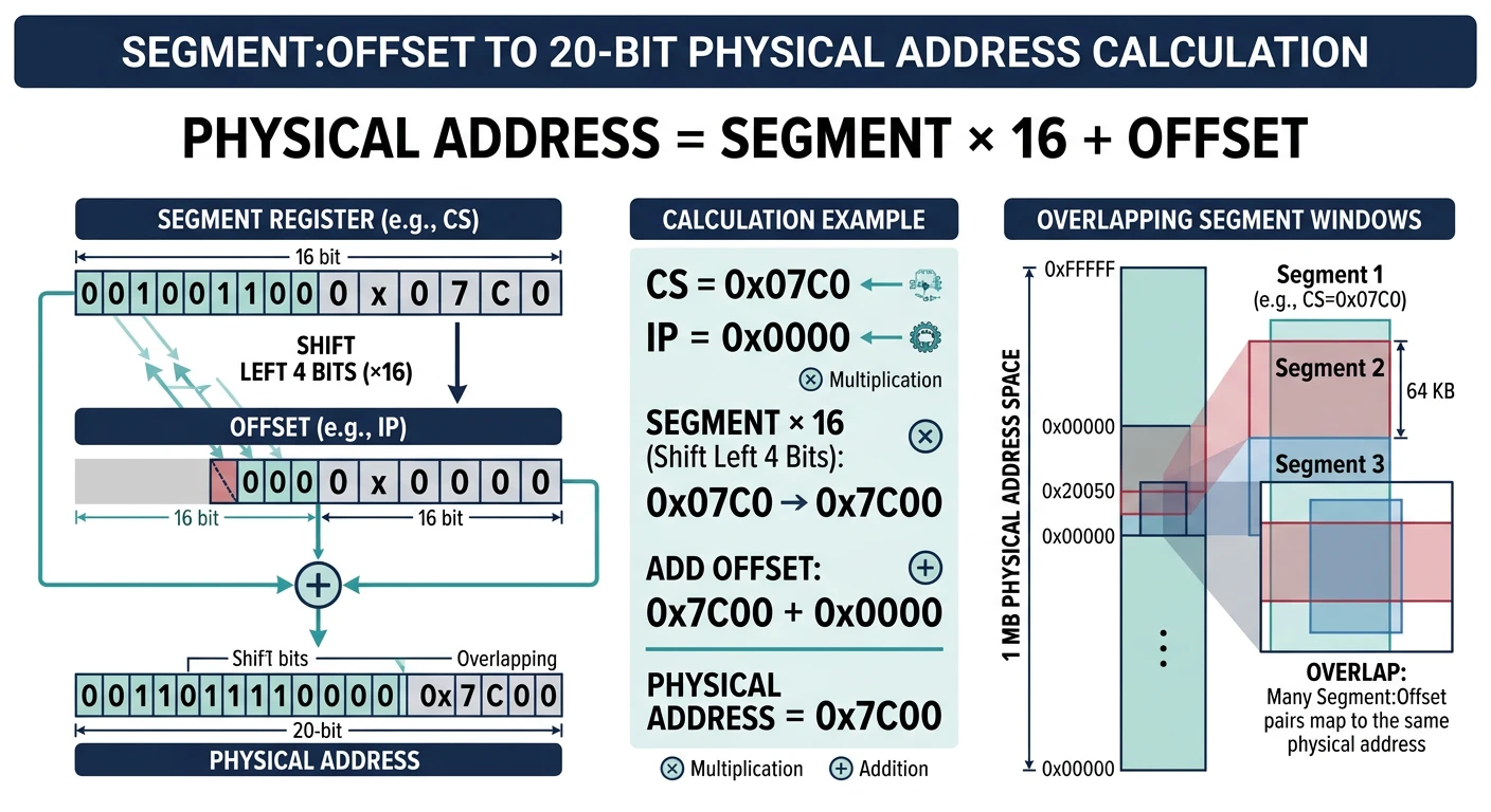
Segment:offset addressing combines a 16-bit segment and 16-bit offset to form a 20-bit physical address, enabling 1MB access from 16-bit registers
The Segmentation Model
The Intel 8086 had a problem: it wanted to address 1MB of memory, but its registers were only 16 bits (max value: 65,535 = 64KB). The solution? Segmentation.
THE PROBLEM:
═══════════════════════════════════════════════════════════════
16-bit register → Maximum value: 65,535 (0xFFFF)
But we want to address: 1,048,576 bytes (0xFFFFF) = 1MB

That requires 20 bits!

THE SOLUTION: Segment:Offset Addressing
═══════════════════════════════════════════════════════════════
Combine TWO 16-bit values to create a 20-bit address:

    Segment Register (16-bit)   ×16   =  20-bit base
  +        Offset (16-bit)            =  16-bit offset
  ────────────────────────────────────────────────────
                                      =  20-bit physical address

Formula: Physical Address = (Segment × 16) + Offset
         Physical Address = (Segment << 4) + Offset
Address Calculation Examples
Example 1: Address 0x1234:0x5678
    Segment: 0x1234 × 16 = 0x12340
  + Offset:  0x5678
  ─────────────────────────────────
  Physical:  0x179B8

Example 2: Boot sector location 0x0000:0x7C00
    Segment: 0x0000 × 16 = 0x00000
  + Offset:  0x7C00
  ─────────────────────────────────
  Physical:  0x07C00  (31,744 in decimal)

Example 3: Video memory 0xB800:0x0000
    Segment: 0xB800 × 16 = 0xB8000
  + Offset:  0x0000
  ─────────────────────────────────
  Physical:  0xB8000  (VGA text mode buffer)
Overlapping Segments: Multiple segment:offset pairs can point to the same physical address! 0x0000:0x7C00, 0x07C0:0x0000, and 0x0100:0x6C00 all refer to physical address 0x7C00. This is a common source of bugs.
Segment Registers
The CPU has dedicated registers for holding segment values:
SEGMENT REGISTERS
═══════════════════════════════════════════════════════════════
Register    Name                Primary Use
──────────────────────────────────────────────────────────────
CS          Code Segment        Where instructions are fetched from
                                (Used with IP: CS:IP = next instruction)

DS          Data Segment        Default segment for data access
                                (mov ax, [variable] uses DS)

SS          Stack Segment       Where the stack lives
                                (Used with SP: SS:SP = stack top)

ES          Extra Segment       Additional data segment
                                (Often used with string operations)

FS, GS      Extra Segments      Added in 386 (not available in 8086)
═══════════════════════════════════════════════════════════════
Code to initialize segment registers:
; Standard bootloader segment initialization
; BIOS loads us at 0x0000:0x7C00, but we want clear segments
[BITS 16]
[ORG 0x7C00]

start:
    ; Clear interrupts during segment setup
    cli

    ; Initialize all segment registers to 0
    xor ax, ax      ; AX = 0
    mov ds, ax      ; Data segment = 0
    mov es, ax      ; Extra segment = 0
    mov ss, ax      ; Stack segment = 0
    mov sp, 0x7C00  ; Stack pointer just below our code
                    ; Stack grows DOWN from 0x7C00 to 0x0500

    ; Re-enable interrupts
    sti

    ; Now DS:variable refers to physical address 0x0000 + variable
    ; SS:SP points to physical address 0x7C00 (grows down)
Memory Map with Segments
Here's how to think about the standard real mode memory layout with segments:
REAL MODE MEMORY WITH COMMON SEGMENTS
═══════════════════════════════════════════════════════════════

Physical     Segment:Offset    Description
Address      Address
──────────────────────────────────────────────────────────────
0xFFFFF      N/A              ← Top of 1MB (limit of real mode)
   │
0xF0000      0xF000:0x0000    ← BIOS ROM area begins
   │         ...
0xC0000      0xC000:0x0000    ← Video BIOS, Option ROMs
   │
0xB8000      0xB800:0x0000    ← VGA Text Mode Video Memory
   │                            (Write here to display text!)
0xA0000      0xA000:0x0000    ← VGA Graphics Mode Memory
   │
   │         Free conventional memory (~638KB)
   │         Load your kernel somewhere in here
   │
0x10000      0x1000:0x0000    ← Common kernel load point (64KB boundary)
   │
0x07E00      0x0000:0x7E00    ← End of boot sector
0x07C00      0x0000:0x7C00    ← Boot sector loaded here by BIOS
   │                            (Your bootloader code starts here)
0x00500      0x0000:0x0500    ← End of BIOS Data Area
   │                            Stack typically lives between
   │                            0x0500 and 0x7C00
0x00400      0x0040:0x0000    ← BIOS Data Area (256 bytes)
0x00000      0x0000:0x0000    ← Interrupt Vector Table (1KB)
═══════════════════════════════════════════════════════════════
BIOS Interrupt Services
Without an operating system, how do you print to the screen or read from a disk? You use BIOS interrupts - a collection of pre-written functions stored in your motherboard's firmware.
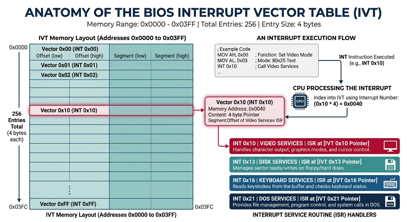
BIOS interrupt services: the CPU looks up the handler address in the IVT, then jumps to the firmware routine for screen, disk, or keyboard I/O
Interrupt Vector Table (IVT)
The first 1KB of memory (addresses 0x0000-0x03FF) contains the Interrupt Vector Table: 256 entries, each pointing to an interrupt handler:
INTERRUPT VECTOR TABLE (IVT) LAYOUT
═══════════════════════════════════════════════════════════════
Address         Interrupt    Description
──────────────────────────────────────────────────────────────
0x0000-0x0003   INT 0        Divide by zero handler
0x0004-0x0007   INT 1        Single step (debug)
0x0008-0x000B   INT 2        NMI (Non-Maskable Interrupt)
0x000C-0x000F   INT 3        Breakpoint
...
0x0040-0x0043   INT 0x10     Video services (BIOS)
0x0044-0x0047   INT 0x11     Equipment list
0x0048-0x004B   INT 0x12     Memory size
0x004C-0x004F   INT 0x13     Disk services (BIOS)
...
0x0080-0x0083   INT 0x20     DOS terminate program
0x0084-0x0087   INT 0x21     DOS services
...

Each entry is 4 bytes: Offset (2 bytes) + Segment (2 bytes)
═══════════════════════════════════════════════════════════════
Video Services (INT 10h)
The most commonly used BIOS interrupt for output is INT 10h:
; ═══════════════════════════════════════════════════════════════
; INT 10h - VIDEO BIOS SERVICES
; ═══════════════════════════════════════════════════════════════

; ─────────────────────────────────────────────────────────────────
; Function 0Eh: Teletype Output (print one character)
; ─────────────────────────────────────────────────────────────────
; Input:  AH = 0Eh (function number)
;         AL = character to print
;         BH = page number (usually 0)
;         BL = foreground color (graphics mode only)
; Output: None
; ─────────────────────────────────────────────────────────────────

print_char:
    mov ah, 0x0E        ; Teletype function
    mov al, 'A'         ; Character to print
    mov bh, 0           ; Page 0
    int 0x10            ; Call BIOS
    ret

; ─────────────────────────────────────────────────────────────────
; Function 00h: Set Video Mode
; ─────────────────────────────────────────────────────────────────
; Input:  AH = 00h
;         AL = mode number
;              03h = 80x25 text mode, 16 colors
;              13h = 320x200 graphics, 256 colors
; Output: None
; ─────────────────────────────────────────────────────────────────

set_video_mode:
    mov ah, 0x00
    mov al, 0x03        ; 80x25 text mode
    int 0x10
    ret

; ─────────────────────────────────────────────────────────────────
; Function 02h: Set Cursor Position
; ─────────────────────────────────────────────────────────────────
; Input:  AH = 02h
;         BH = page number
;         DH = row (0-24)
;         DL = column (0-79)
; Output: None
; ─────────────────────────────────────────────────────────────────

move_cursor:
    mov ah, 0x02
    mov bh, 0           ; Page 0
    mov dh, 10          ; Row 10
    mov dl, 20          ; Column 20
    int 0x10
    ret
Complete Print String Function:
; Print a null-terminated string
; Input: SI = pointer to string
print_string:
    pusha                   ; Save all registers
    mov ah, 0x0E            ; Teletype function
.loop:
    lodsb                   ; Load next byte from [SI] into AL, increment SI
    test al, al             ; Check if AL is zero (null terminator)
    jz .done                ; If zero, we're done
    int 0x10                ; Print the character
    jmp .loop               ; Continue with next character
.done:
    popa                    ; Restore all registers
    ret

; Print a newline (carriage return + line feed)
print_newline:
    pusha
    mov ah, 0x0E
    mov al, 0x0D            ; Carriage return
    int 0x10
    mov al, 0x0A            ; Line feed
    int 0x10
    popa
    ret
Disk Services (INT 13h)
To load more code beyond the 512-byte boot sector, you need disk access:
; ═══════════════════════════════════════════════════════════════
; INT 13h - DISK BIOS SERVICES
; ═══════════════════════════════════════════════════════════════

; ─────────────────────────────────────────────────────────────────
; Function 02h: Read Sectors (CHS addressing)
; ─────────────────────────────────────────────────────────────────
; Input:  AH = 02h
;         AL = number of sectors to read (1-128)
;         CH = cylinder number (0-1023, low 8 bits)
;         CL = sector number (1-63, bits 0-5)
;              high cylinder bits (bits 6-7)
;         DH = head number (0-255)
;         DL = drive number (0x00=floppy A, 0x80=first HDD)
;         ES:BX = destination buffer address
;
; Output: CF = 0 if successful, 1 if error
;         AH = status code
;         AL = number of sectors actually read
; ─────────────────────────────────────────────────────────────────

read_sectors_chs:
    mov ah, 0x02        ; Read sectors function
    mov al, 5           ; Read 5 sectors
    mov ch, 0           ; Cylinder 0
    mov cl, 2           ; Start at sector 2 (sector 1 is boot sector)
    mov dh, 0           ; Head 0
    mov dl, 0x80        ; First hard disk (use 0x00 for floppy)

    ; Set destination buffer at 0x1000:0x0000 = physical 0x10000
    mov bx, 0x1000
    mov es, bx
    xor bx, bx          ; ES:BX = 0x1000:0x0000

    int 0x13            ; Call BIOS
    jc disk_error       ; Jump if carry flag set (error)
    ret

; ─────────────────────────────────────────────────────────────────
; Function 42h: Extended Read (LBA addressing) - modern disks
; ─────────────────────────────────────────────────────────────────
; Input:  AH = 42h
;         DL = drive number
;         DS:SI = pointer to Disk Address Packet (DAP)
;
; Disk Address Packet structure:
;   Offset  Size   Description
;   0       1      Size of packet (16 bytes)
;   1       1      Reserved (0)
;   2       2      Number of sectors to read
;   4       4      Transfer buffer (segment:offset)
;   8       8      Starting LBA (64-bit)
; ─────────────────────────────────────────────────────────────────

read_sectors_lba:
    mov ah, 0x42        ; Extended read function
    mov dl, 0x80        ; First hard disk
    mov si, dap         ; Point to Disk Address Packet
    int 0x13
    jc disk_error
    ret

dap:
    db 0x10             ; Size of DAP (16 bytes)
    db 0                ; Reserved
    dw 5                ; Number of sectors to read
    dw 0x0000           ; Offset of buffer
    dw 0x1000           ; Segment of buffer (0x1000:0x0000)
    dq 1                ; Starting LBA (sector 1 = after boot sector)
CHS vs LBA: CHS (Cylinder-Head-Sector) is the old addressing method limited to 8GB. LBA (Logical Block Addressing) uses a simple sector number and supports modern large drives. Always check for LBA support with INT 13h function 41h before using function 42h.
Boot Sector Structure
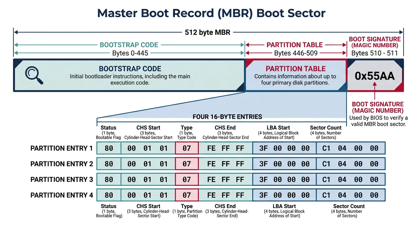
The boot sector is the first 512 bytes of your bootable disk. Understanding its structure is essential for writing a bootloader.
MBR boot sector layout: 446 bytes of bootstrap code, four 16-byte partition entries, and the 0xAA55 magic boot signature
Modern systems use GPT instead of MBR. GPT still has a "protective MBR" in sector 0 for backward compatibility, but the real partition table is in sectors 1-33:
GPT DISK LAYOUT
═══════════════════════════════════════════════════════════════
Sector    Contents
───────────────────────────────────────────────────────────────
0         Protective MBR (for legacy BIOS compatibility)
1         Primary GPT Header
2-33      Partition entries (128 bytes each, 128 max)
...       Actual partitions (your data)
-33 to -2 Backup partition entries
-1        Backup GPT Header
═══════════════════════════════════════════════════════════════

For UEFI boot (Phase 12), we'll create a proper GPT disk with an
EFI System Partition. For now with BIOS, we use MBR.
Boot Signature (0x55AA)
The BIOS checks for the boot signature at offset 510-511. Without it, the BIOS won't recognize your disk as bootable:
; The boot signature must be at bytes 510-511 of the boot sector
; BIOS checks for 0x55 at offset 510 and 0xAA at offset 511

; Method 1: Using times directive
times 510-($-$$) db 0    ; Pad with zeros until offset 510
dw 0xAA55                ; Boot signature (note: little-endian!)

; Method 2: Explicit positioning
SECTION .text
; ... your bootloader code ...

; At the end of the file:
SECTION .bootsig start=510
    db 0x55
    db 0xAA
Little-Endian Alert: x86 is little-endian, so dw 0xAA55 stores bytes as 0x55, 0xAA in memory - which is exactly what BIOS expects!
Writing Your First Bootloader
Now let's write a real, working bootloader from scratch!
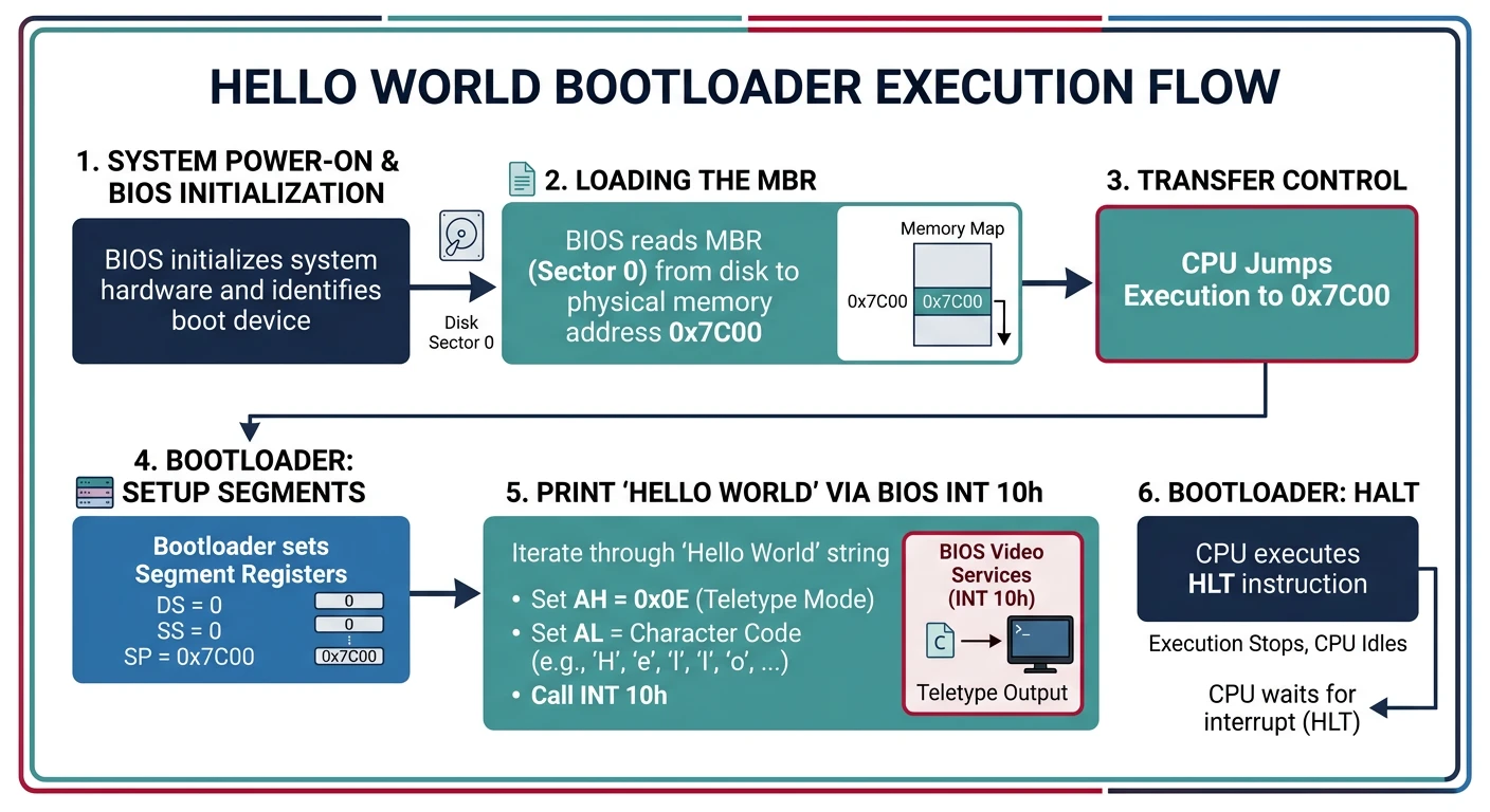
Bootloader execution flow: BIOS loads the 512-byte boot sector to 0x7C00, the CPU begins executing our NASM assembly, and characters appear on screen via INT 0x10
Complete Hello World Bootloader
Complete Working Code
boot.asm - Your First Bootloader
; ═══════════════════════════════════════════════════════════════
; boot.asm - Complete Hello World Bootloader
; Assemble: nasm -f bin boot.asm -o boot.img
; Run:      qemu-system-i386 -fda boot.img
; ═══════════════════════════════════════════════════════════════

[BITS 16]               ; We're in 16-bit real mode
[ORG 0x7C00]            ; BIOS loads us at this address

; ─────────────────────────────────────────────────────────────────
; ENTRY POINT
; ─────────────────────────────────────────────────────────────────
start:
    ; Disable interrupts while setting up segments
    cli

    ; Initialize segment registers
    xor ax, ax          ; AX = 0
    mov ds, ax          ; Data segment = 0
    mov es, ax          ; Extra segment = 0
    mov ss, ax          ; Stack segment = 0
    mov sp, 0x7C00      ; Stack grows down from 0x7C00

    ; Re-enable interrupts
    sti

    ; Clear screen
    call clear_screen

    ; Print welcome message
    mov si, msg_welcome
    call print_string

    ; Print system info
    mov si, msg_info
    call print_string

    ; Display available memory
    call print_memory_size

    ; Print prompt
    mov si, msg_prompt
    call print_string

    ; Wait for keypress then reboot
    call wait_keypress

    ; Reboot (jump to reset vector)
    jmp 0xFFFF:0x0000

; ─────────────────────────────────────────────────────────────────
; FUNCTIONS
; ─────────────────────────────────────────────────────────────────

; Clear the screen and set cursor to top-left
clear_screen:
    pusha
    mov ah, 0x00        ; Set video mode
    mov al, 0x03        ; 80x25 text mode
    int 0x10
    popa
    ret

; Print null-terminated string
; Input: SI = pointer to string
print_string:
    pusha
    mov ah, 0x0E        ; Teletype output
.loop:
    lodsb               ; Load byte from SI into AL, increment SI
    test al, al         ; Is it null?
    jz .done
    int 0x10            ; Print character
    jmp .loop
.done:
    popa
    ret

; Print hexadecimal number
; Input: AX = number to print
print_hex:
    pusha
    mov cx, 4           ; 4 hex digits
    mov bx, hex_chars   ; Lookup table
.loop:
    rol ax, 4           ; Rotate left 4 bits
    push ax
    and al, 0x0F        ; Mask lower 4 bits
    xlat                ; AL = [BX + AL]
    mov ah, 0x0E
    int 0x10
    pop ax
    loop .loop
    popa
    ret

hex_chars: db '0123456789ABCDEF'

; Print memory size in KB
print_memory_size:
    pusha

    ; INT 12h returns memory size in KB in AX
    int 0x12            ; Get conventional memory size

    ; Print the number
    mov si, msg_memory
    call print_string
    call print_hex

    mov si, msg_kb
    call print_string

    popa
    ret

; Wait for any keypress
wait_keypress:
    pusha
    mov ah, 0x00        ; Wait for keypress
    int 0x16            ; Keyboard BIOS service
    popa
    ret

; ─────────────────────────────────────────────────────────────────
; DATA
; ─────────────────────────────────────────────────────────────────
msg_welcome:  db '=================================', 13, 10
              db '  My First Bootloader!', 13, 10
              db '  Running on bare metal x86', 13, 10
              db '=================================', 13, 10, 0

msg_info:     db 13, 10
              db 'CPU is in 16-bit Real Mode', 13, 10
              db 'Segment registers initialized', 13, 10
              db 'BIOS interrupts available', 13, 10, 0

msg_memory:   db 13, 10, 'Conventional memory: 0x', 0
msg_kb:       db ' KB', 13, 10, 0

msg_prompt:   db 13, 10, 'Press any key to reboot...', 0

; ─────────────────────────────────────────────────────────────────
; BOOT SECTOR PADDING AND SIGNATURE
; ─────────────────────────────────────────────────────────────────
times 510-($-$$) db 0   ; Pad to 510 bytes
dw 0xAA55               ; Boot signature
Reading Additional Sectors from Disk
512 bytes isn't enough for a real bootloader. Here's how to load more code:
; ═══════════════════════════════════════════════════════════════
; boot_stage1.asm - Loads additional code from disk
; This boot sector loads 'stage2' from sectors 2-6 to 0x1000
; ═══════════════════════════════════════════════════════════════

[BITS 16]
[ORG 0x7C00]

STAGE2_SEGMENT  equ 0x1000
STAGE2_OFFSET   equ 0x0000
SECTORS_TO_READ equ 5

start:
    cli
    xor ax, ax
    mov ds, ax
    mov es, ax
    mov ss, ax
    mov sp, 0x7C00
    sti

    ; Save boot drive number (BIOS passes it in DL)
    mov [boot_drive], dl

    ; Print loading message
    mov si, msg_loading
    call print_string

    ; Load stage 2 from disk
    call load_stage2
    jc .disk_error

    ; Jump to stage 2
    mov si, msg_jumping
    call print_string

    ; Far jump to stage 2 at 0x1000:0x0000
    jmp STAGE2_SEGMENT:STAGE2_OFFSET

.disk_error:
    mov si, msg_error
    call print_string
    jmp $               ; Hang on error

load_stage2:
    ; Try up to 3 times
    mov di, 3

.retry:
    ; Reset disk system
    xor ah, ah
    mov dl, [boot_drive]
    int 0x13

    ; Set up read parameters
    mov ah, 0x02                ; Read sectors
    mov al, SECTORS_TO_READ     ; Number of sectors
    mov ch, 0                   ; Cylinder 0
    mov cl, 2                   ; Start at sector 2
    mov dh, 0                   ; Head 0
    mov dl, [boot_drive]        ; Drive number

    ; Set destination buffer
    mov bx, STAGE2_SEGMENT
    mov es, bx
    mov bx, STAGE2_OFFSET

    ; Perform read
    int 0x13
    jnc .success        ; No carry = success

    ; Retry on failure
    dec di
    jnz .retry

    ; All retries failed
    stc                 ; Set carry flag (error)
    ret

.success:
    clc                 ; Clear carry flag (success)
    ret

print_string:
    pusha
    mov ah, 0x0E
.loop:
    lodsb
    test al, al
    jz .done
    int 0x10
    jmp .loop
.done:
    popa
    ret

; Data
boot_drive:  db 0
msg_loading: db 'Loading stage 2...', 13, 10, 0
msg_jumping: db 'Jumping to stage 2!', 13, 10, 0
msg_error:   db 'Disk read error!', 0

times 510-($-$$) db 0
dw 0xAA55
Chain Loading: Building a Two-Stage Bootloader
Stage 2 runs at address 0x10000 and has room for more complex code:
; ═══════════════════════════════════════════════════════════════
; stage2.asm - Second stage bootloader
; Loaded at 0x1000:0x0000 (physical address 0x10000)
; ═══════════════════════════════════════════════════════════════

[BITS 16]
[ORG 0x0000]            ; Loaded at offset 0 within segment 0x1000

stage2_start:
    ; Set up segments for Stage 2
    mov ax, 0x1000
    mov ds, ax
    mov es, ax

    ; Print stage 2 message
    mov si, msg_stage2
    call print_string

    ; Enable A20 line (required to access memory above 1MB)
    call enable_a20

    ; From here, you would:
    ; 1. Load the kernel from disk
    ; 2. Set up the GDT
    ; 3. Switch to protected mode
    ; 4. Jump to kernel

    ; For now, just hang
    mov si, msg_ready
    call print_string
    jmp $

enable_a20:
    ; Fast A20 gate method (works on most systems)
    in al, 0x92
    or al, 2
    out 0x92, al
    ret

print_string:
    pusha
    mov ah, 0x0E
.loop:
    lodsb
    test al, al
    jz .done
    int 0x10
    jmp .loop
.done:
    popa
    ret

msg_stage2: db 'Stage 2 loaded successfully!', 13, 10, 0
msg_ready:  db 'Ready for protected mode...', 13, 10, 0

; Pad to fill entire 5 sectors (2560 bytes)
times 2560-($-$$) db 0
Building and Running the Two-Stage Bootloader
# Assemble both stages
nasm -f bin boot_stage1.asm -o stage1.bin
nasm -f bin stage2.asm -o stage2.bin

# Combine into disk image
cat stage1.bin stage2.bin > bootloader.img

# Pad to floppy size (optional, for some emulators)
truncate -s 1440K bootloader.img

# Run in QEMU
qemu-system-i386 -fda bootloader.img

# Debug with GDB
qemu-system-i386 -fda bootloader.img -s -S &
gdb -ex "target remote localhost:1234" \
    -ex "set architecture i8086" \
    -ex "break *0x7c00" \
    -ex "continue"
Exercises & What You Can Build
Hands-On Project
Phase 2 Deliverables
A custom bootloader that runs on real hardware
Low-level disk reading logic using BIOS INT 13h
Hardware interaction without any operating system
Understanding of the first 1MB of memory layout
Exercise 1: Enhanced Hello World
Modify the hello world bootloader to:
Print in different colors (use attribute bytes at 0xB8000)