We use cookies to enhance your browsing experience, serve personalized content, and analyze our traffic.
By clicking "Accept All", you consent to our use of cookies. See our
Privacy Policy
for more information.
Phase 3 Goals: By the end of this phase, you'll have transitioned your bootloader from 16-bit real mode to 32-bit protected mode, set up proper memory segmentation, and successfully called your first C function in kernel space.
In Phase 2, you mastered real mode - the CPU's 16-bit compatibility mode with direct hardware access but severe limitations. Now it's time to break free. Protected mode is the gateway to modern operating system development: 32-bit computing, gigabytes of memory, hardware-enforced security, and the ability to write your kernel in C.
The leap from real mode to protected mode: unlocking 32-bit registers, 4GB address space, memory protection rings, and hardware-enforced security
Protected Mode Analogy: Moving to a Modern House
Real mode is like living in a single-room cabin where everything is in one space - no privacy, no separation, and if something catches fire, you lose everything.
Protected mode is like moving to a modern house with separate rooms:
Room doors (memory protection) - Each room (process) has walls and doors
Security system (privilege rings) - Only the homeowner (kernel) has master keys
Multiple floors (privilege levels) - Ring 0 is the penthouse, Ring 3 is the lobby
Bigger property (4GB address space) - Room for a mansion, not just a cabin
Key Insight: Protected mode isn't just about more memory. It gives us hardware-enforced memory protection, privilege levels (rings), and the ability to use high-level languages like C effectively. It's the foundation for all modern operating systems.
Why Protected Mode?
Every modern operating system - Windows, Linux, macOS - runs in protected mode (or its 64-bit successor, long mode). Here's why:
Memory Freedom
32-bit addresses: Access up to 4GB RAM (vs 1MB)
Flat memory model: No more segment:offset math
Virtual memory ready: Foundation for paging
Hardware Protection
Ring 0-3: Kernel vs user privileges
Segment limits: Bounds checking
Page-level protection: Read/write/execute
Real vs Protected Mode
Feature
Real Mode
Protected Mode
Bit Width
16-bit registers
32-bit registers (EAX, EBX, etc.)
Address Space
1MB (20-bit)
4GB (32-bit)
Memory Model
Segmented (segment:offset)
Flat (or segmented with descriptors)
Protection
None - any code can access anything
Hardware enforced - rings 0-3
BIOS Access
Direct via INT instructions
Not available (must use drivers)
Segment Registers
Contain actual addresses
Contain selectors into GDT
Multitasking
Software only (cooperative)
Hardware-assisted (TSS)
Point of No Return: Once you enter protected mode, you lose access to BIOS interrupts. That's why we did all our BIOS-based disk loading in Phase 2. In protected mode, you must write your own drivers or use BIOS services through a V86 mode wrapper (complex!).
Global Descriptor Table (GDT)
The GDT is the heart of protected mode. It's a table in memory that defines memory segments - their base address, size, permissions, and type. Before switching to protected mode, you must set up at least a minimal GDT.
GDT structure: the null descriptor at index 0, followed by code and data segment descriptors each defining base, limit, type, and privilege level
GDT Analogy: Building Access Control
Think of the GDT as a security desk in a large building:
Each "segment" is like a floor pass defining which floors you can access
The base address is which floor the pass starts from
The limit is how many floors you can access
The access rights determine if you can read, write, or execute
The privilege level is like employee vs. guest badge
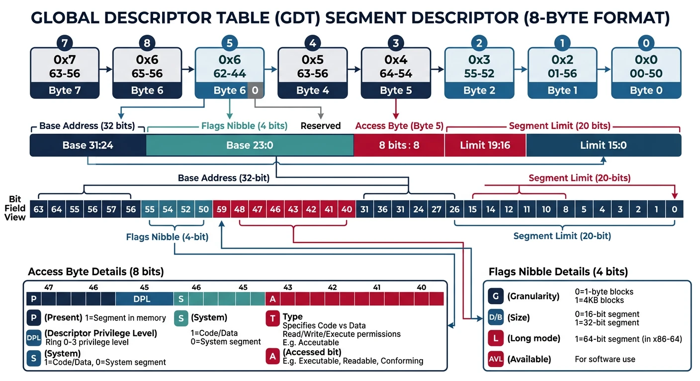
GDT Structure
The GDT is an array of 8-byte entries called segment descriptors. The CPU locates the GDT using a special register:
Each segment descriptor is 8 bytes packed with information. This is one of the most complex structures in x86:
SEGMENT DESCRIPTOR FORMAT (8 bytes = 64 bits)
═══════════════════════════════════════════════════════════════

Byte 7    Byte 6    Byte 5    Byte 4    Byte 3-2   Byte 1-0
┌────────┬────────┬────────┬────────┬──────────┬───────────┐
│Base    │Flags + │Access  │Base    │Base      │Limit      │
│[31:24] │Limit   │Byte    │[23:16] │[15:0]    │[15:0]     │
│        │[19:16] │        │        │          │           │
└────────┴────────┴────────┴────────┴──────────┴───────────┘

ACCESS BYTE (Byte 5)
═══════════════════════════════════════════════════════════════
Bit 7   Bit 6-5   Bit 4    Bit 3    Bit 2    Bit 1    Bit 0
┌─────┬─────────┬───────┬────────┬────────┬────────┬────────┐
│  P  │   DPL   │   S   │   E    │   DC   │   RW   │   A    │
└─────┴─────────┴───────┴────────┴────────┴────────┴────────┘

P  = Present (1 = segment is valid)
DPL = Descriptor Privilege Level (0=highest, 3=lowest)
S  = Descriptor type (1=code/data, 0=system)
E  = Executable (1=code segment, 0=data segment)
DC = Direction/Conforming
RW = Read/Write (code: readable, data: writable)
A  = Accessed (CPU sets this when segment is accessed)

FLAGS (Byte 6, upper nibble)
═══════════════════════════════════════════════════════════════
Bit 7    Bit 6    Bit 5    Bit 4
┌──────┬────────┬────────┬────────┐
│  G   │  D/B   │   L    │  AVL   │
└──────┴────────┴────────┴────────┘

G   = Granularity (0=byte, 1=4KB pages)
D/B = Default operation size (0=16-bit, 1=32-bit)
L   = Long mode (1=64-bit, only for code segments)
AVL = Available for system software
Here's a complete, well-documented GDT for protected mode:
; ═══════════════════════════════════════════════════════════════
; gdt.asm - Global Descriptor Table for Protected Mode
; ═══════════════════════════════════════════════════════════════

; Define segment selectors (offsets into GDT)
CODE_SEG equ gdt_code - gdt_start   ; 0x08
DATA_SEG equ gdt_data - gdt_start   ; 0x10

gdt_start:
; ─────────────────────────────────────────────────────────────────
; Null Descriptor (REQUIRED - CPU checks for this)
; ─────────────────────────────────────────────────────────────────
gdt_null:
    dq 0x0                          ; 8 bytes of zeros

; ─────────────────────────────────────────────────────────────────
; Code Segment Descriptor
; Base = 0x00000000, Limit = 0xFFFFF (4GB with granularity)
; Access: Present, Ring 0, Code, Execute/Read
; Flags: 4KB granularity, 32-bit
; ─────────────────────────────────────────────────────────────────
gdt_code:
    dw 0xFFFF               ; Limit (bits 0-15)
    dw 0x0000               ; Base (bits 0-15)
    db 0x00                 ; Base (bits 16-23)
    db 10011010b            ; Access byte:
                            ;   1 = Present
                            ;   00 = Ring 0
                            ;   1 = Code/Data segment
                            ;   1 = Executable (code)
                            ;   0 = Non-conforming
                            ;   1 = Readable
                            ;   0 = Accessed (CPU sets)
    db 11001111b            ; Flags + Limit (bits 16-19):
                            ;   1 = 4KB granularity
                            ;   1 = 32-bit segment
                            ;   0 = Not 64-bit
                            ;   0 = Available
                            ;   1111 = Limit bits 16-19
    db 0x00                 ; Base (bits 24-31)

; ─────────────────────────────────────────────────────────────────
; Data Segment Descriptor
; Base = 0x00000000, Limit = 0xFFFFF (4GB with granularity)
; Access: Present, Ring 0, Data, Read/Write
; Flags: 4KB granularity, 32-bit
; ─────────────────────────────────────────────────────────────────
gdt_data:
    dw 0xFFFF               ; Limit (bits 0-15)
    dw 0x0000               ; Base (bits 0-15)
    db 0x00                 ; Base (bits 16-23)
    db 10010010b            ; Access byte:
                            ;   1 = Present
                            ;   00 = Ring 0
                            ;   1 = Code/Data segment
                            ;   0 = Data (not executable)
                            ;   0 = Grows up
                            ;   1 = Writable
                            ;   0 = Accessed
    db 11001111b            ; Flags + Limit (bits 16-19)
    db 0x00                 ; Base (bits 24-31)

gdt_end:

; ─────────────────────────────────────────────────────────────────
; GDT Descriptor (pointer loaded into GDTR)
; ─────────────────────────────────────────────────────────────────
gdt_descriptor:
    dw gdt_end - gdt_start - 1      ; Size (limit = size - 1)
    dd gdt_start                    ; Linear address of GDT
Flat Memory Model: Both our code and data segments have base=0 and limit=4GB. This gives us a "flat" memory model where segment:offset = linear address. Modern operating systems use this approach and rely on paging for protection instead of segmentation.
Memory Segments in Protected Mode
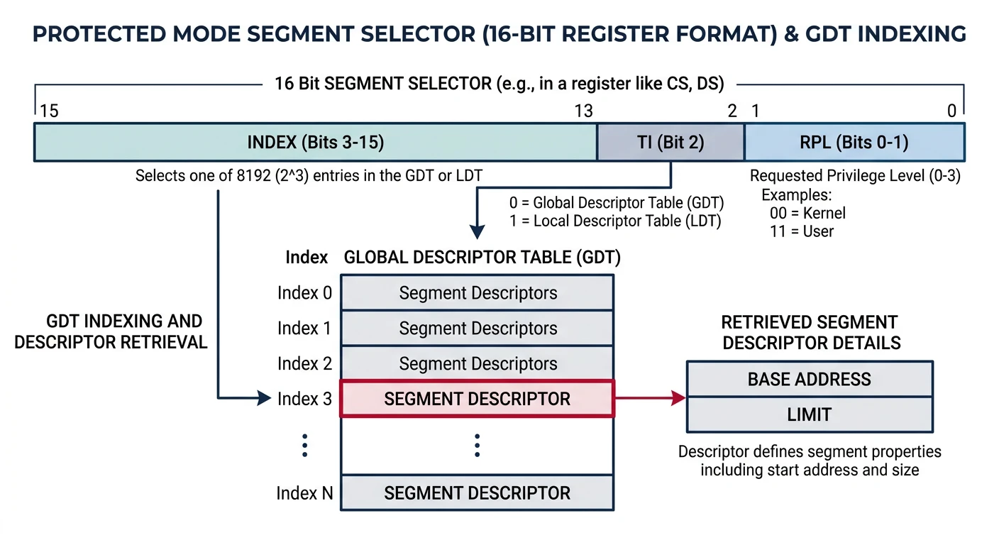
In protected mode, segment registers don't hold addresses directly. Instead, they hold selectors - indexes into the GDT that point to segment descriptors.
Segment selectors: a 16-bit value encoding the GDT index, table indicator, and requested privilege level to look up the full segment descriptor
SEGMENT SELECTOR FORMAT (16 bits)
═══════════════════════════════════════════════════════════════
Bits 15-3    Bit 2    Bits 1-0
┌───────────┬───────┬──────────┐
│   Index   │  TI   │   RPL    │
└───────────┴───────┴──────────┘

Index = Entry number in GDT (bits 3-15)
TI    = Table Indicator (0=GDT, 1=LDT)
RPL   = Requested Privilege Level (0-3)

EXAMPLES:
───────────────────────────────────────────────────────────────
0x08 = 0000 0000 0000 1000b = Index 1, GDT, Ring 0 → Code segment
0x10 = 0000 0000 0001 0000b = Index 2, GDT, Ring 0 → Data segment
0x1B = 0000 0000 0001 1011b = Index 3, GDT, Ring 3 → User code
Code Segment (CS)
The code segment defines where executable code can run. In protected mode, the processor checks that every instruction fetch comes from an executable segment:
; After entering protected mode, CS must be loaded with a far jump
; This flushes the CPU's prefetch queue and loads the new selector

; Jump to 32-bit code using code segment selector
jmp CODE_SEG:protected_mode_entry

[bits 32]
protected_mode_entry:
    ; Now running in 32-bit protected mode!
    ; CS automatically loaded with CODE_SEG (0x08)

    ; The code segment descriptor specifies:
    ; - Base address: 0x00000000
    ; - Limit: 0xFFFFF × 4KB = 4GB
    ; - Execute and read permissions
    ; - Ring 0 (kernel mode)
Data Segment (DS, ES, FS, GS)
Data segments control access to memory for reading and writing data:
[bits 32]
protected_mode_entry:
    ; Load data segment selector into all data segment registers
    mov ax, DATA_SEG        ; DATA_SEG = 0x10
    mov ds, ax              ; Data segment
    mov es, ax              ; Extra segment
    mov fs, ax              ; F segment (386+)
    mov gs, ax              ; G segment (386+)

    ; Now we can access memory using DS:
    mov eax, [0x100000]     ; Read from 1MB mark
    mov [0xB8000], eax      ; Write to video memory

    ; With flat model (base=0), addresses are linear:
    ; DS:0x100000 = 0x00000000 + 0x100000 = 0x100000
Stack Segment (SS)
The stack segment controls stack operations (PUSH, POP, CALL, RET):
[bits 32]
setup_stack:
    ; Load stack segment selector
    mov ax, DATA_SEG        ; Use same segment as data
    mov ss, ax              ; Stack segment

    ; Set up stack pointer
    ; Stack typically placed at high memory
    mov esp, 0x90000        ; Stack top at 576KB
    mov ebp, esp            ; Base pointer = stack pointer

    ; Now we can use the stack:
    push eax                ; Push register
    push dword 0x12345678   ; Push immediate
    call some_function      ; CALL uses stack
    pop eax                 ; Pop value

    ; Stack grows DOWN: high addresses → low addresses
    ; PUSH: ESP decreases by 4, then value stored at [ESP]
    ; POP:  Value loaded from [ESP], then ESP increases by 4
STACK LAYOUT (after some operations)
═══════════════════════════════════════════════════════════════
                    High Memory
    0x90000     ┌─────────────────────┐ ← Initial ESP, EBP
                │ (unused)            │
    0x8FFFC     ├─────────────────────┤ ← ESP after PUSH dword
                │ Pushed Value        │
    0x8FFF8     ├─────────────────────┤ ← ESP after CALL
                │ Return Address      │
                ├─────────────────────┤
                │ Function's locals   │
                ├─────────────────────┤ ← Current ESP in function
                │ ...                 │
                    Low Memory
The A20 Line Gate
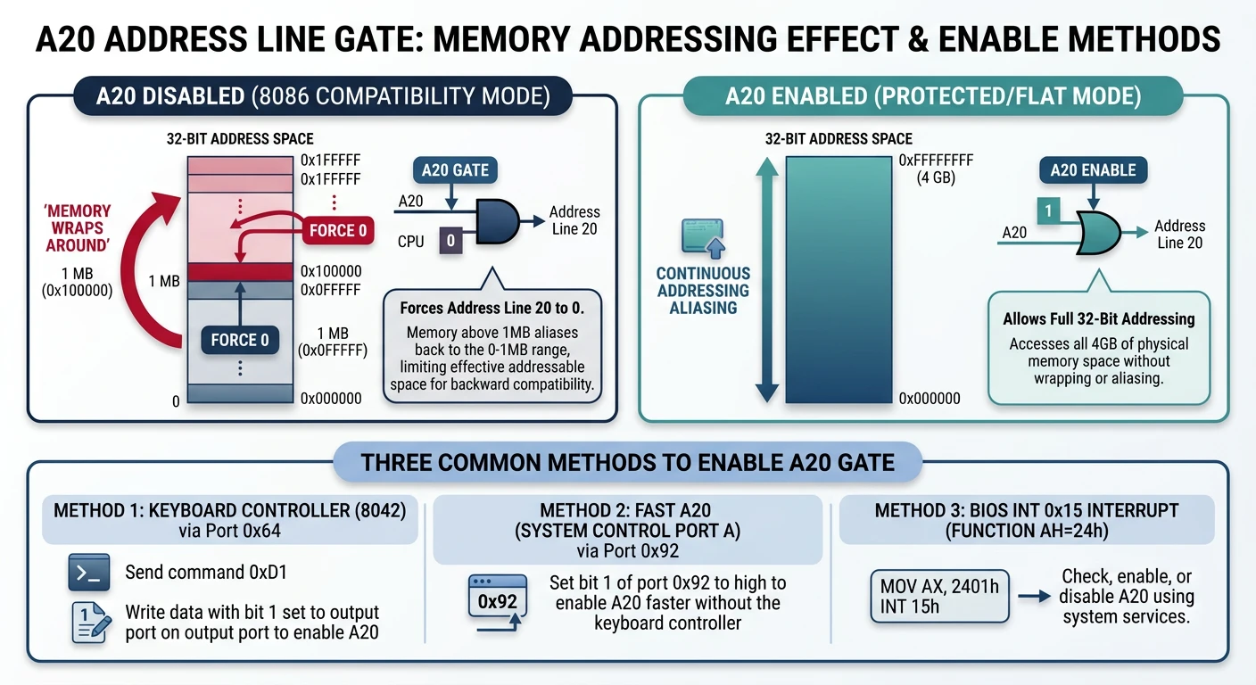
Before you can access memory above 1MB, you must enable the A20 line. This is one of the strangest quirks in x86 history!
The A20 gate: with A20 disabled, address line 20 is forced to zero causing memory to wrap at 1MB; enabling it unlocks the full address space
Historical Context: A Compatibility Hack
The Story of A20
In the early 1980s, some DOS programs relied on a bug in the 8086:
The 8086 had 20 address lines (A0-A19) = 1MB addressable
Addresses that wrapped around (e.g., 0xFFFF:0x0010 = 0x100000) would wrap to 0x00000
Some programs depended on this wraparound behavior!
When the 80286 introduced 24 address lines (A0-A23), IBM couldn't break old software. Their solution? A physical gate on the A20 line that could force address bit 20 to zero, preserving the wraparound behavior. This gate was controlled through... the keyboard controller! 🤦
A20 LINE EFFECT
═══════════════════════════════════════════════════════════════
Memory Address      With A20 Disabled    With A20 Enabled
───────────────────────────────────────────────────────────────
0x000000-0x0FFFFF   Normal access        Normal access
0x100000            Wraps to 0x000000!   Accesses 0x100000
0x100001            Wraps to 0x000001!   Accesses 0x100001
0x1FFFFF            Wraps to 0x0FFFFF!   Accesses 0x1FFFFF

Without A20 enabled, you can only use odd megabytes:
0-1MB, 2-3MB, 4-5MB... (even megabytes wrap to 0-1MB)
Methods to Enable A20
There are several ways to enable A20. You should try them in order of speed/reliability:
A20 Gate Enable Procedure
flowchart TD
    A["Start: Enable A20 Gate"] --> B{"Try Keyboard
Controller 0x64"}
    B -->|Success| G["A20 Enabled"]
    B -->|Fail| C{"Try Fast A20
Port 0x92"}
    C -->|Success| G
    C -->|Fail| D{"Try BIOS
INT 15h AX=2401h"}
    D -->|Success| G
    D -->|Fail| E["A20 Enable Failed"]
    G --> F["Verify: Read/Write
Above 1MB Boundary"]
    F --> H["Proceed to
Protected Mode"]

    style G fill:#e8f4f4,stroke:#3B9797
    style E fill:#fff5f5,stroke:#BF092F
    style H fill:#f0f4f8,stroke:#16476A
Method 1: BIOS Function (Simplest)
; Try BIOS INT 15h first (fastest if supported)
enable_a20_bios:
    mov ax, 0x2401          ; A20 enable function
    int 0x15
    jnc .success            ; CF=0 means success
    ; Fall through to next method if failed
.success:
    ret
Method 2: Fast A20 (System Port - Works on Most Systems)
; Fast A20 via System Control Port A (0x92)
; WARNING: Can cause crashes on some older systems
enable_a20_fast:
    in al, 0x92             ; Read System Control Port A
    test al, 2              ; Check if A20 already enabled
    jnz .done               ; Skip if already enabled
    or al, 2                ; Set A20 bit
    and al, 0xFE            ; Clear bit 0 (avoid system reset!)
    out 0x92, al            ; Write back
.done:
    ret
Method 3: Keyboard Controller (Most Compatible)
; Enable A20 via keyboard controller (8042)
; This is the original method - works on everything
enable_a20_keyboard:
    cli                         ; Disable interrupts

    call .wait_input            ; Wait for controller ready
    mov al, 0xAD                ; Disable keyboard
    out 0x64, al

    call .wait_input
    mov al, 0xD0                ; Read output port command
    out 0x64, al

    call .wait_output           ; Wait for data available
    in al, 0x60                 ; Read output port value
    push eax                    ; Save it

    call .wait_input
    mov al, 0xD1                ; Write output port command
    out 0x64, al

    call .wait_input
    pop eax                     ; Restore output port value
    or al, 2                    ; Set A20 gate bit
    out 0x60, al                ; Write to output port

    call .wait_input
    mov al, 0xAE                ; Re-enable keyboard
    out 0x64, al

    call .wait_input
    sti                         ; Re-enable interrupts
    ret

; Wait for keyboard controller input buffer to be empty
.wait_input:
    in al, 0x64
    test al, 2
    jnz .wait_input
    ret

; Wait for keyboard controller output buffer to have data
.wait_output:
    in al, 0x64
    test al, 1
    jz .wait_output
    ret
Testing if A20 is Enabled:
; Check if A20 is enabled by comparing wrapped addresses
check_a20:
    pushad

    ; Write different values to 0x007C00 and 0x107C00
    ; If A20 is disabled, these are the same physical address!

    mov edi, 0x007C00           ; Low address
    mov esi, 0x107C00           ; High address (would wrap if A20 off)

    mov [edi], dword 0x12345678
    mov [esi], dword 0x87654321

    cmp dword [edi], 0x12345678 ; Check if it was overwritten

    popad
    je .a20_enabled             ; Values different = A20 enabled
    ret                         ; Return (A20 disabled)
.a20_enabled:
    stc                         ; Set carry flag = enabled
    ret
Important: Always test if A20 is enabled after attempting to enable it. Some systems need multiple attempts, and the fast method can fail silently. A robust bootloader tries all methods in sequence.
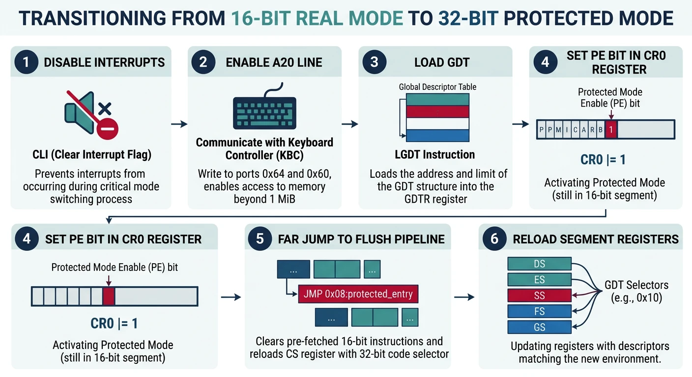
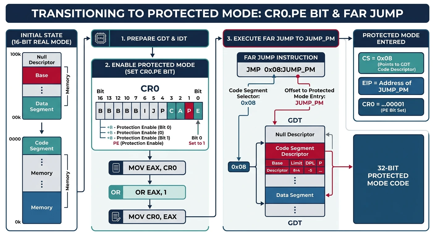
Switching to 32-Bit Protected Mode
Now we're ready for the big moment - the actual mode switch! This is accomplished by modifying the CR0 control register and performing a far jump.
The mode switch sequence: set CR0.PE bit to 1, then execute a far jump to flush the pipeline and load the new code segment selector
CR0 Control Register
CR0 REGISTER (Control Register 0)
═══════════════════════════════════════════════════════════════
Bit   Name   Description
───────────────────────────────────────────────────────────────
0     PE     Protection Enable - SET THIS TO ENTER PROTECTED MODE
1     MP     Monitor Coprocessor
2     EM     Emulate FPU
3     TS     Task Switched
4     ET     Extension Type (486+: hardwired to 1)
5     NE     Numeric Error
16    WP     Write Protect (prevent kernel writing read-only pages)
18    AM     Alignment Mask
29    NW     Not Write-through (cache)
30    CD     Cache Disable
31    PG     Paging Enable (for virtual memory, Phase 6)
═══════════════════════════════════════════════════════════════

To enter protected mode: Set bit 0 (PE)
To enable paging later: Set bit 31 (PG) - requires page tables first!
The Far Jump: Why It's Critical
After setting PE in CR0, you must perform a far jump. Here's why:
CPU Pipeline & Prefetch Queue: The CPU prefetches and decodes instructions ahead of time. After changing to protected mode, these prefetched instructions are still decoded as 16-bit real mode instructions! A far jump flushes the pipeline and prefetch queue, forcing the CPU to fetch and decode new instructions in 32-bit mode.
; ═══════════════════════════════════════════════════════════════
; THE COMPLETE MODE SWITCH SEQUENCE
; ═══════════════════════════════════════════════════════════════

[bits 16]
switch_to_protected_mode:
    ; Step 1: Disable interrupts
    ; We can't handle interrupts during mode transition!
    cli

    ; Step 2: Enable A20 line (already covered above)
    call enable_a20_fast

    ; Step 3: Load the GDT
    lgdt [gdt_descriptor]

    ; Step 4: Set PE (Protection Enable) bit in CR0
    mov eax, cr0
    or eax, 1               ; Set bit 0 (PE)
    mov cr0, eax

    ; Step 5: FAR JUMP to load CS with protected mode selector
    ; This flushes the prefetch queue and enters 32-bit mode
    jmp CODE_SEG:protected_mode_start

; ═══════════════════════════════════════════════════════════════
; 32-BIT PROTECTED MODE CODE
; ═══════════════════════════════════════════════════════════════
[bits 32]
protected_mode_start:
    ; Step 6: Load all data segment registers
    mov ax, DATA_SEG        ; DATA_SEG = 0x10
    mov ds, ax
    mov es, ax
    mov fs, ax
    mov gs, ax
    mov ss, ax

    ; Step 7: Set up the stack
    mov esp, 0x90000        ; Stack at 576KB
    mov ebp, esp

    ; Step 8: Jump to kernel!
    ; At this point:
    ; - We're in 32-bit protected mode
    ; - GDT is loaded with flat segments
    ; - Stack is set up
    ; - A20 is enabled
    ; - Interrupts are disabled (we'll set up IDT in Phase 5)

    call kernel_main        ; Call our C kernel!

    ; If kernel returns (shouldn't happen), halt
    jmp $
Common Mode Switch Bugs
Symptom
Likely Cause
Triple fault / reboot
GDT not set up correctly, null descriptor accessed
Hangs after mode switch
Missing far jump, data segments not loaded
Random memory corruption
A20 not enabled, stack in wrong location
Works in QEMU, not real hardware
Fast A20 method not supported, use keyboard controller
C Runtime Setup: From Assembly to C
Now the exciting part - calling C code from your bootloader! To do this properly, you need a linker script, proper compilation flags, and understanding of the C calling convention.
Linker Script
The linker script tells the linker how to arrange your code in memory:
/* linker.ld - Kernel Linker Script */

/* Entry point - the symbol the bootloader will jump to */
ENTRY(kernel_main)

/* Memory layout */
SECTIONS {
    /* Kernel loads at 1MB mark (0x100000) - above real mode area */
    . = 0x100000;

    /* Code section - executable instructions */
    .text BLOCK(4K) : ALIGN(4K) {
        *(.multiboot)       /* Multiboot header (if used) */
        *(.text)            /* All .text sections from all objects */
    }

    /* Read-only data - string literals, const variables */
    .rodata BLOCK(4K) : ALIGN(4K) {
        *(.rodata)
        *(.rodata.*)
    }

    /* Initialized data - global variables with initial values */
    .data BLOCK(4K) : ALIGN(4K) {
        *(.data)
    }

    /* Uninitialized data - global variables without initial values */
    .bss BLOCK(4K) : ALIGN(4K) {
        *(COMMON)
        *(.bss)
        /* Reserve space for kernel stack */
        . = ALIGN(16);
        _stack_bottom = .;
        . += 16K;           /* 16KB stack */
        _stack_top = .;
    }

    /* End of kernel - useful for memory management later */
    _kernel_end = .;
}
Writing Your First C Kernel Code
Here's a complete, working C kernel that displays colored text:
/* kernel.c - First C Kernel Code */

/* VGA text mode constants */
#define VGA_WIDTH  80
#define VGA_HEIGHT 25
#define VGA_MEMORY ((volatile char*)0xB8000)

/* VGA colors */
enum vga_color {
    VGA_BLACK = 0,
    VGA_BLUE = 1,
    VGA_GREEN = 2,
    VGA_CYAN = 3,
    VGA_RED = 4,
    VGA_MAGENTA = 5,
    VGA_BROWN = 6,
    VGA_LIGHT_GREY = 7,
    VGA_DARK_GREY = 8,
    VGA_LIGHT_BLUE = 9,
    VGA_LIGHT_GREEN = 10,
    VGA_LIGHT_CYAN = 11,
    VGA_LIGHT_RED = 12,
    VGA_LIGHT_MAGENTA = 13,
    VGA_YELLOW = 14,
    VGA_WHITE = 15
};

/* Current cursor position */
static int cursor_x = 0;
static int cursor_y = 0;
static char current_color = 0x0F; /* White on black */

/* Helper: create VGA color byte */
static inline char make_color(enum vga_color fg, enum vga_color bg) {
    return fg | (bg << 4);
}

/* Helper: create VGA entry (character + color) */
static inline short make_vga_entry(char c, char color) {
    return (short)c | ((short)color << 8);
}

/* Clear the screen */
void clear_screen(void) {
    short* video = (short*)VGA_MEMORY;
    short blank = make_vga_entry(' ', current_color);

    for (int i = 0; i < VGA_WIDTH * VGA_HEIGHT; i++) {
        video[i] = blank;
    }
    cursor_x = 0;
    cursor_y = 0;
}

/* Print a single character */
void putchar(char c) {
    short* video = (short*)VGA_MEMORY;

    if (c == '\n') {
        cursor_x = 0;
        cursor_y++;
    } else if (c == '\r') {
        cursor_x = 0;
    } else if (c == '\t') {
        cursor_x = (cursor_x + 8) & ~7; /* Tab to next 8-column boundary */
    } else {
        video[cursor_y * VGA_WIDTH + cursor_x] = make_vga_entry(c, current_color);
        cursor_x++;
    }

    /* Handle line wrap */
    if (cursor_x >= VGA_WIDTH) {
        cursor_x = 0;
        cursor_y++;
    }

    /* Handle scroll (simple: just wrap for now) */
    if (cursor_y >= VGA_HEIGHT) {
        /* TODO: Implement scrolling in Phase 4 */
        cursor_y = 0; /* Wrap around for now */
    }
}

/* Print a null-terminated string */
void print(const char* str) {
    while (*str) {
        putchar(*str++);
    }
}

/* Set the text color */
void set_color(enum vga_color fg, enum vga_color bg) {
    current_color = make_color(fg, bg);
}

/* ═══════════════════════════════════════════════════════════════
 * KERNEL ENTRY POINT - Called from bootloader assembly
 * ═══════════════════════════════════════════════════════════════ */
void kernel_main(void) {
    /* Clear screen and set up display */
    clear_screen();

    /* Print welcome banner in cyan */
    set_color(VGA_LIGHT_CYAN, VGA_BLACK);
    print("===============================================\n");
    print("      Welcome to MyOS - Phase 3 Complete!      \n");
    print("===============================================\n\n");

    /* Print system info in white */
    set_color(VGA_WHITE, VGA_BLACK);
    print("Status: Running in 32-bit Protected Mode\n");
    print("Memory: 4GB address space available\n");
    print("Stack:  Set up at 0x90000\n\n");

    /* Print next steps in yellow */
    set_color(VGA_YELLOW, VGA_BLACK);
    print("Next: Phase 4 - Proper display drivers!\n");

    /* Print footer in green */
    set_color(VGA_LIGHT_GREEN, VGA_BLACK);
    print("\nKernel halted. System stable.\n");

    /* Halt the CPU - never return from kernel_main */
    while (1) {
        __asm__ volatile ("hlt");
    }
}
Cross-Compiler Required: You need an i686-elf-gcc cross-compiler. A host GCC might produce code that depends on your OS! See Phase 1 for setup instructions.
Exercises & What You Can Build
Phase 3 Achievement: You've built a minimal kernel that boots through your bootloader, transitions to protected mode, and executes C code that writes directly to video memory!