CPU Modes Overview
x86 Operating Modes
| Mode | Registers | Address Space | Intro |
|---|---|---|---|
| Real Mode | 16-bit | 1 MB | 8086 (1978) |
| Protected Mode | 32-bit | 4 GB | 386 (1985) |
| Long Mode | 64-bit | 256 TB | AMD64 (2003) |
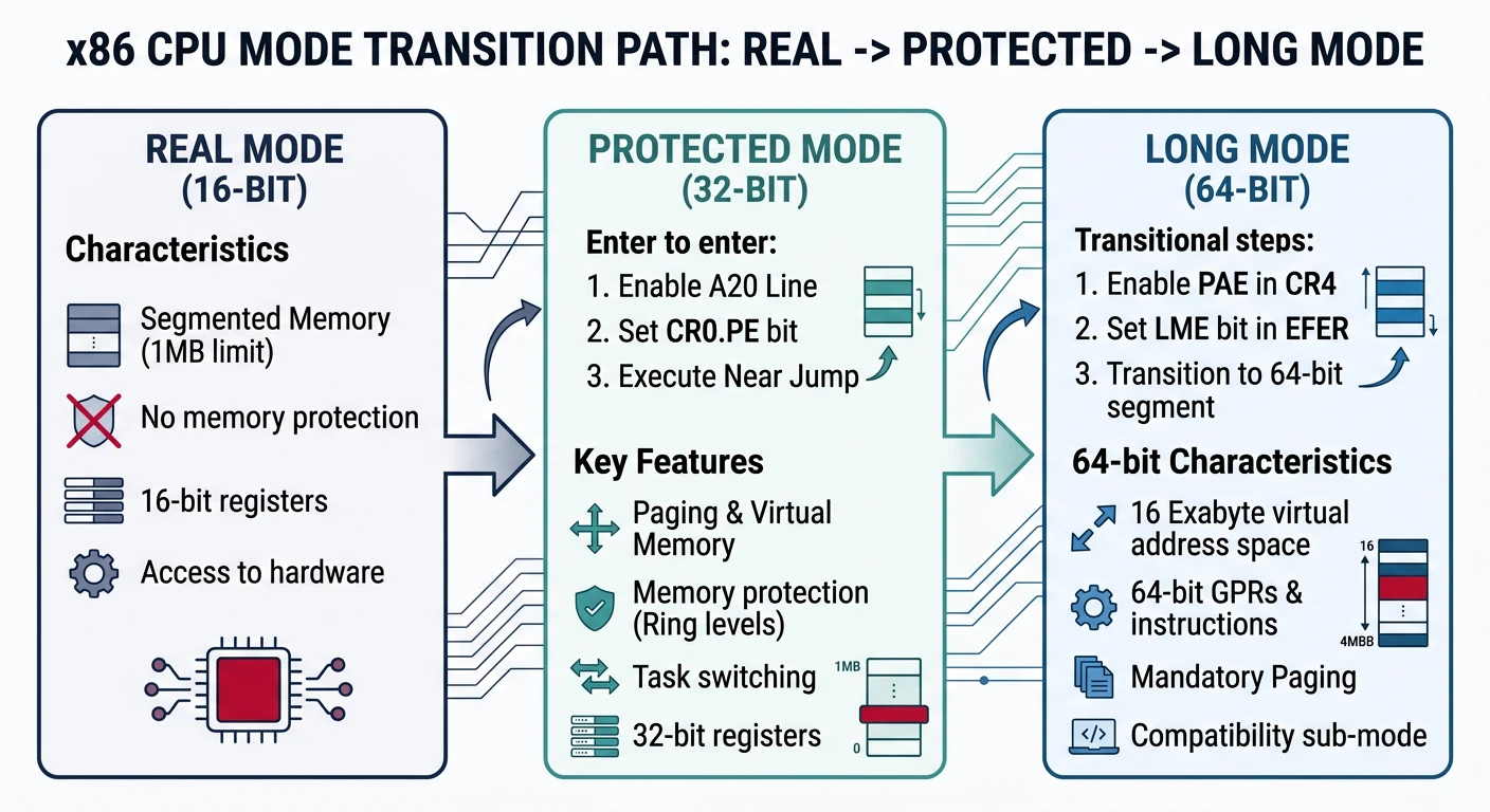
Master CPU operating modes: real mode (16-bit), protected mode (32-bit), and long mode (64-bit). Understand the GDT, paging, segmentation, privilege rings, and memory protection mechanisms.
| Mode | Registers | Address Space | Intro |
|---|---|---|---|
| Real Mode | 16-bit | 1 MB | 8086 (1978) |
| Protected Mode | 32-bit | 4 GB | 386 (1985) |
| Long Mode | 64-bit | 256 TB | AMD64 (2003) |
; Real mode addressing: segment:offset
; Physical Address = (segment × 16) + offset
; Example: 0x07C0:0x0000 = 0x7C00 (boot sector)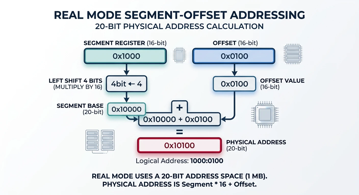
; GDT entry structure (8 bytes)
gdt_null:
    dq 0                    ; Null descriptor (required)

gdt_code:
    dw 0xFFFF               ; Limit 0-15
    dw 0x0000               ; Base 0-15
    db 0x00                 ; Base 16-23
    db 10011010b            ; Access: present, ring 0, code, readable
    db 11001111b            ; Flags + Limit 16-19
    db 0x00                 ; Base 24-31

gdt_data:
    dw 0xFFFF
    dw 0x0000
    db 0x00
    db 10010010b            ; Access: present, ring 0, data, writable
    db 11001111b
    db 0x00

gdt_descriptor:
    dw $ - gdt_null - 1     ; Size
    dd gdt_null             ; Address
Segmentation divides memory into logical segments. Think of it like chapters in a book—each chapter (segment) has its own starting point and rules about who can read it.
15                              3   2   1 0
┌────────────────────────────────┬───┬─────┐
│           Index                │ TI│ RPL │
│         (13 bits)              │   │     │
└────────────────────────────────┴───┴─────┘
Index: Entry number in GDT/LDT (0-8191)
TI:    Table Indicator (0=GDT, 1=LDT)
RPL: Requested Privilege Level (0-3)| Bits | Field | Description |
|---|---|---|
| 0-15 | Limit 0:15 | Segment size (low 16 bits) |
| 16-31 | Base 0:15 | Base address (low 16 bits) |
| 32-39 | Base 16:23 | Base address (mid 8 bits) |
| 40-47 | Access Byte | Type and permissions |
| 48-51 | Limit 16:19 | Segment size (high 4 bits) |
| 52-55 | Flags | G, D/B, L, AVL |
| 56-63 | Base 24:31 | Base address (high 8 bits) |
Bit 7: P (Present) - Segment is in memory
Bit 6-5: DPL (Privilege) - Ring level 0-3
Bit 4: S (Descriptor) - 1=code/data, 0=system
Bit 3: E (Executable) - 1=code, 0=data
Bit 2: DC (Direction/Conf) - Data: grow direction, Code: conforming
Bit 1: RW (Read/Write) - Code: readable, Data: writable
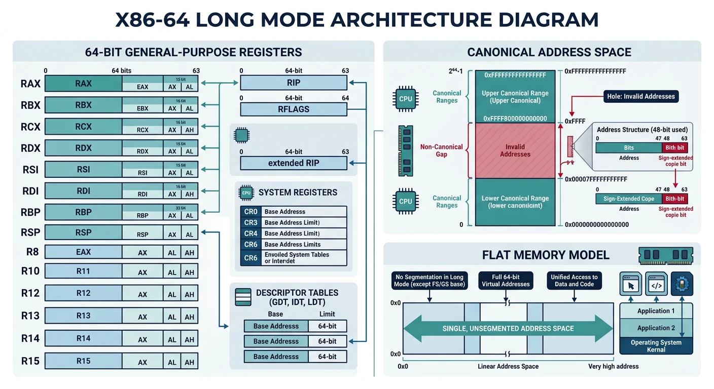
Bit 0: A (Accessed) - CPU sets when segment accessedLong mode is the native operating mode of x86-64 CPUs. It provides 64-bit registers, a flat memory model, and access to vastly more memory than 32-bit protected mode.
| Sub-Mode | Code Size | Registers | Use Case |
|---|---|---|---|
| 64-bit Mode | 64-bit default, 32-bit via prefix | Full R8-R15, RIP-relative | Native 64-bit applications |
| Compatibility Mode | 32/16-bit | EAX-EDI only | Run legacy 32-bit apps |
Although 64-bit mode has 64-bit pointers, current CPUs only implement 48 bits of virtual address space. Valid addresses must be "canonical"—bits 48-63 must match bit 47.
48-bit Virtual Address Space:

Canonical High: 0xFFFF800000000000 - 0xFFFFFFFFFFFFFFFF (kernel space)
                ↑ bits 48-63 = 1 (sign extension of bit 47)

Non-Canonical:  0x0001000000000000 - 0xFFFE7FFFFFFFFFFF (FORBIDDEN)
                ↑ causes #GP fault if accessed!

Canonical Low:  0x0000000000000000 - 0x00007FFFFFFFFFFF (user space)
↑ bits 48-63 = 0 (sign extension of bit 47); 64-bit mode code example
bits 64
section .data
message db "Hello from long mode!", 10, 0
msg_len equ $ - message
section .text
global _start
_start:
; Syscall: write(1, message, msg_len)
mov rax, 1 ; syscall number (write)
mov rdi, 1 ; fd = stdout
lea rsi, [rel message] ; RIP-relative addressing
mov rdx, msg_len
syscall
; Syscall: exit(0)
mov rax, 60
xor rdi, rdi
syscalllong_mode_hello.asmLinux
nasm -f elf64 long_mode_hello.asm -o long_mode_hello.o
ld long_mode_hello.o -o long_mode_hello
./long_mode_hello
macOS (change _start → _main, write=0x2000004, exit=0x2000001)
nasm -f macho64 long_mode_hello.asm -o long_mode_hello.o
ld -macos_version_min 10.13 -e _main -static long_mode_hello.o -o long_mode_hello
Windows (use Win64 API instead of Linux syscalls)
nasm -f win64 long_mode_hello.asm -o long_mode_hello.obj
link /subsystem:console /entry:_start long_mode_hello.obj /out:long_mode_hello.exe
Paging is the cornerstone of modern memory management. It translates virtual addresses (what your program sees) to physical addresses (actual RAM locations), enabling memory protection, isolation, and more memory than physically exists.
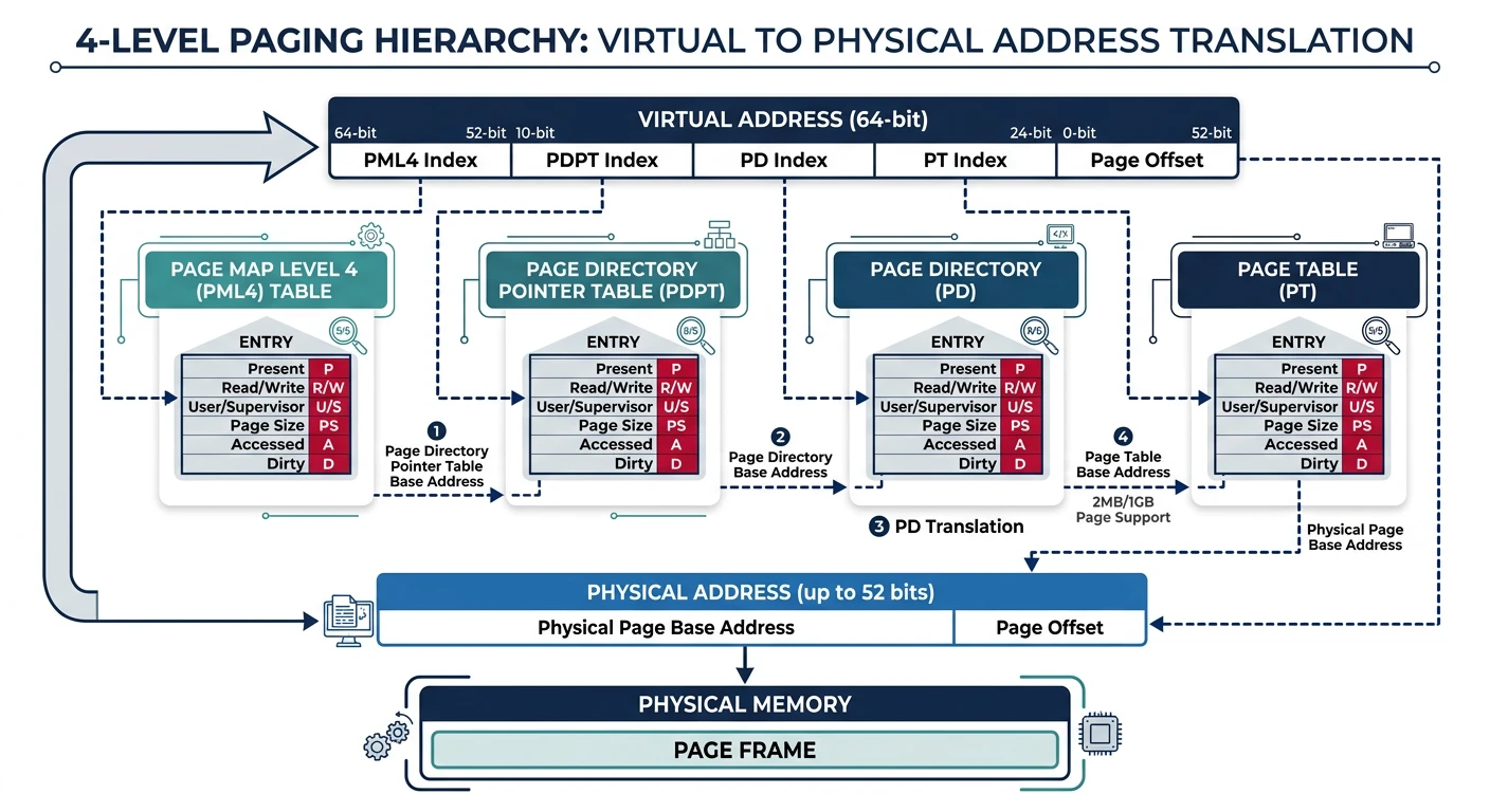
Virtual Address (48-bit):
┌─────────┬─────────┬─────────┬─────────┬──────────────┐
│ PML4    │  PDPT   │   PD    │   PT    │    Offset    │
│ 9 bits  │  9 bits │  9 bits │  9 bits │   12 bits    │
└────┬────┴────┬────┴────┬────┴────┬────┴──────┬───────┘
     │         │         │         │           │
     ▼         ▼         ▼         ▼           ▼
┌─────────┐ ┌─────────┐ ┌─────────┐ ┌─────────┐ ┌─────────┐
│  PML4   │→│  PDPT   │→│   PD    │→│   PT    │→│ 4KB Page│
│  Table  │ │  Table  │ │  Table  │ │  Table  │ │ in RAM  │
└─────────┘ └─────────┘ └─────────┘ └─────────┘ └─────────┘
    512       512         512         512
   entries   entries     entries     entries

CR3 register holds physical address of PML4 table| Bit(s) | Name | Meaning |
|---|---|---|
| 0 | P | Present (1=in memory) |
| 1 | R/W | Read/Write (0=read-only) |
| 2 | U/S | User/Supervisor (1=user accessible) |
| 3 | PWT | Page Write-Through |
| 4 | PCD | Page Cache Disable |
| 5 | A | Accessed (set by CPU) |
| 6 | D | Dirty (page written to) |
| 7 | PS | Page Size (1=large page) |
| 12-51 | Address | Physical page frame address |
| 63 | NX | No Execute (1=non-executable) |
Walking 4 levels of page tables for every memory access would be impossibly slow. The TLB is a hardware cache that stores recent virtual→physical translations.
INVLPG (single page) or reload CR3 (flush entire TLB). On multi-core systems, this requires expensive inter-processor interrupts.
; Invalidate TLB entry for a specific address
mov rax, [virtual_address]
invlpg [rax]              ; Invalidate single page

; Flush entire TLB (reload CR3)
mov rax, cr3
mov cr3, rax ; Writing CR3 flushes TLBWhen the CPU can't complete a page table walk, it raises exception 14 (Page Fault). The error code pushed to the stack tells you what happened:
Page Fault Error Code:
Bit 0 (P):    0 = non-present page, 1 = protection violation
Bit 1 (W/R):  0 = read access, 1 = write access
Bit 2 (U/S):  0 = supervisor mode, 1 = user mode
Bit 3 (RSVD): 1 = reserved bit set in page table
Bit 4 (I/D):  1 = instruction fetch

CR2 register contains the faulting virtual address4KB pages work for most cases, but large allocations benefit from bigger pages:
Huge pages reduce TLB misses dramatically—one TLB entry covers 2MB instead of 4KB!
x86 implements hardware-enforced privilege levels to isolate the kernel from user programs. Think of it like security clearances—higher clearance (lower ring number) grants more access.
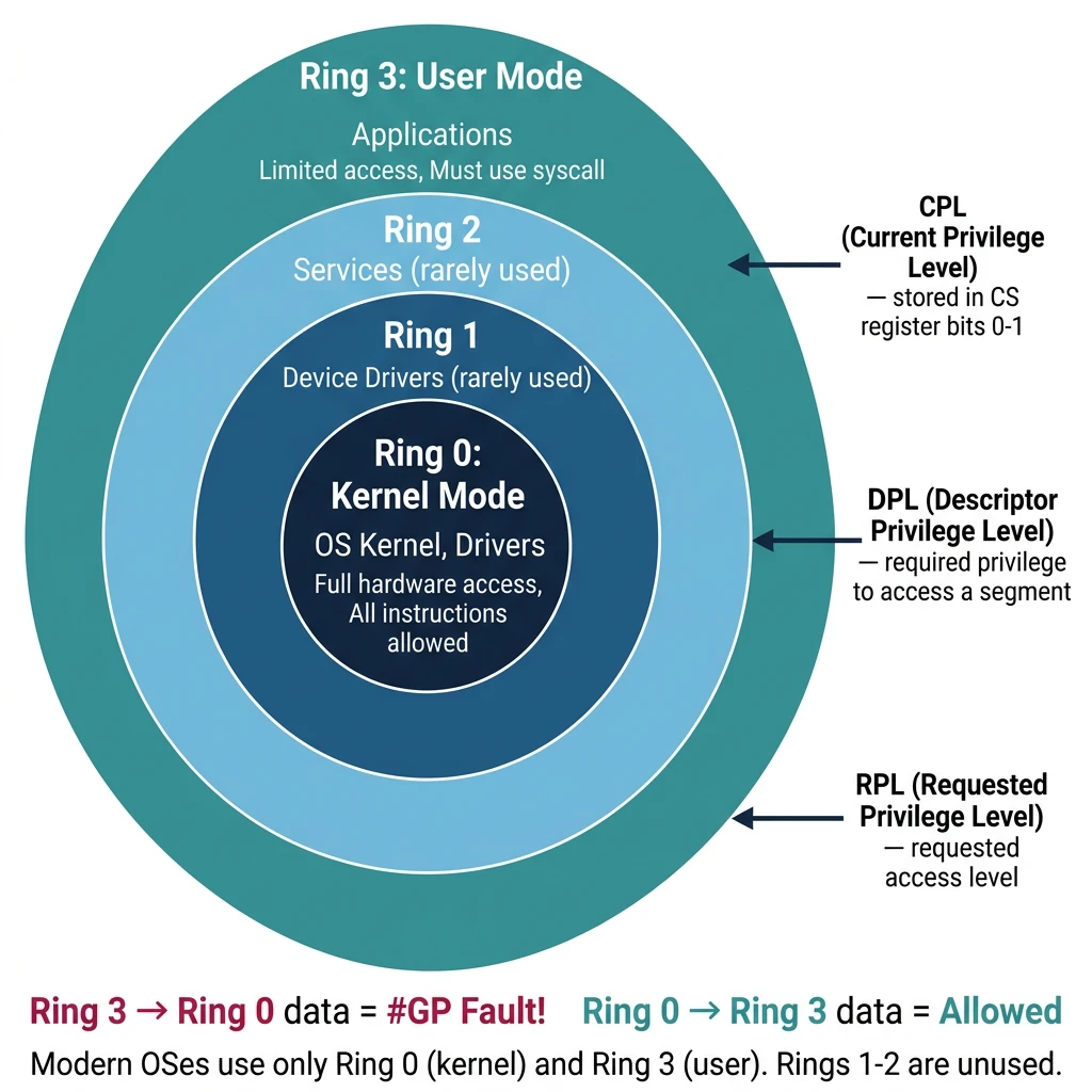
         Ring 0 (Kernel Mode)
        ┌────────────────────┐
        │  OS Kernel, Drivers │  ← Full hardware access
        │  All instructions   │
        └────────┬───────────┘
                 │
         Ring 1-2 (Rarely Used)
        ┌────────────────────┐
        │  Device Drivers*    │  ← Originally for drivers
        │  (unused today)     │    Modern OS: everything Ring 0
        └────────┬───────────┘
                 │
         Ring 3 (User Mode)
        ┌────────────────────┐
        │  Applications       │  ← Limited access
        │  No privileged instr│    Must ask kernel via syscall
└────────────────────┘| Acronym | Name | Stored In | Purpose |
|---|---|---|---|
| CPL | Current Privilege Level | CS register (bits 0-1) | Current code's privilege |
| DPL | Descriptor Privilege Level | Segment descriptor | Required privilege to access |
| RPL | Requested Privilege Level | Segment selector (bits 0-1) | Requested access level |
Data Segment Access:
  CPL ≤ DPL  AND  RPL ≤ DPL  →  Access allowed

Code Segment Access (via JMP/CALL):
  Non-conforming: CPL = DPL
  Conforming:     CPL ≥ DPL (can call from lower privilege)

Examples:
  Ring 3 code accessing Ring 0 data → #GP fault!
  Ring 0 code accessing Ring 3 data → Allowed
  Ring 3 calling Ring 0 code directly → #GP fault!
Ring 3 using SYSCALL to enter Ring 0 → Allowed (controlled entry)HLT (halt CPU), LGDT/LIDT (load descriptor tables), MOV CRx (control registers), IN/OUT (port I/O), WRMSR/RDMSR (model-specific registers). Executing these in Ring 3 triggers #GP.
; User (Ring 3) → Kernel (Ring 0)
; Method 1: Software interrupt (legacy)
int 0x80              ; Linux legacy syscall

; Method 2: SYSCALL instruction (modern, faster)
mov rax, 1            ; syscall number
syscall               ; Enters Ring 0 via MSR-defined entry

; Kernel (Ring 0) → User (Ring 3)
; IRET or SYSRET restores user context and drops privilege
sysretq ; Return from SYSCALL to user modeTry running this privileged instruction in a user-mode program:
section .text
global _start
_start:
    cli               ; Disable interrupts (Ring 0 only!)
    mov rax, 60
    xor rdi, rdi
    syscall
Result: Segmentation fault! The CPU denies CLI in Ring 3.
ring_test.asmLinux
nasm -f elf64 ring_test.asm -o ring_test.o
ld ring_test.o -o ring_test
./ring_test    # Expected: Segmentation fault
macOS (change _start → _main)
nasm -f macho64 ring_test.asm -o ring_test.o
ld -macos_version_min 10.13 -e _main -static ring_test.o -o ring_test
Windows
nasm -f win64 ring_test.asm -o ring_test.obj
link /subsystem:console /entry:_start ring_test.obj /out:ring_test.exeWhen an x86-64 CPU powers on, it starts in 16-bit real mode for BIOS compatibility. Transitioning to 64-bit long mode requires careful setup of multiple CPU features.
┌──────────────┐     ┌──────────────┐     ┌──────────────┐
│  Real Mode   │────→│Protected Mode│────→│  Long Mode   │
│   16-bit     │     │   32-bit     │     │   64-bit     │
│   1MB limit  │     │   4GB limit  │     │   256TB (48b)│
│   No paging  │     │   Paging opt.│     │Paging required│
│   No protect.│     │   Rings 0-3  │     │   Rings 0-3  │
└──────────────┘     └──────────────┘     └──────────────┘
     Steps:               Steps:
     1. Setup GDT         1. Enable PAE
     2. Set CR0.PE=1      2. Setup PML4
     3. Far jump          3. Enable EFER.LME
                          4. Enable CR0.PG
5. Far jump to 64-bitbits 16
org 0x7C00
start:
cli ; Disable interrupts
xor ax, ax
mov ds, ax
mov es, ax
mov ss, ax
mov sp, 0x7C00 ; Stack below bootloader
; ═══════════════════════════════════════════════════════════
; STEP 1: Load GDT
; ═══════════════════════════════════════════════════════════
lgdt [gdt_descriptor]
; ═══════════════════════════════════════════════════════════
; STEP 2: Enable Protected Mode (CR0.PE = 1)
; ═══════════════════════════════════════════════════════════
mov eax, cr0
or eax, 1 ; Set PE bit
mov cr0, eax
jmp 0x08:protected_mode ; Far jump flushes prefetch queue
bits 32
protected_mode:
; ═══════════════════════════════════════════════════════════
; STEP 3: Setup 32-bit segments
; ═══════════════════════════════════════════════════════════
mov ax, 0x10 ; Data segment selector
mov ds, ax
mov es, ax
mov ss, ax
mov esp, 0x90000
; ═══════════════════════════════════════════════════════════
; STEP 4: Enable PAE (required for long mode)
; ═══════════════════════════════════════════════════════════
mov eax, cr4
or eax, (1 << 5) ; CR4.PAE = 1
mov cr4, eax
; ═══════════════════════════════════════════════════════════
; STEP 5: Setup identity-mapped page tables
; ═══════════════════════════════════════════════════════════
; PML4[0] → PDPT
mov edi, 0x1000 ; PML4 at 0x1000
mov eax, 0x2003 ; PDPT address | Present | Writable
stosd
xor eax, eax
mov ecx, 1023
rep stosd ; Clear rest of PML4
; PDPT[0] → PD
mov eax, 0x3003 ; PD address | Present | Writable
stosd
xor eax, eax
mov ecx, 1023
rep stosd
; PD: 512 x 2MB pages = 1GB identity mapped
mov edi, 0x3000
mov eax, 0x83 ; Present | Writable | 2MB page
mov ecx, 512
.pd_loop:
stosd
add edi, 4 ; Skip high 32 bits
add eax, 0x200000 ; Next 2MB
loop .pd_loop
; ═══════════════════════════════════════════════════════════
; STEP 6: Load CR3 with PML4 address
; ═══════════════════════════════════════════════════════════
mov eax, 0x1000
mov cr3, eax
; ═══════════════════════════════════════════════════════════
; STEP 7: Enable Long Mode (EFER.LME = 1)
; ═══════════════════════════════════════════════════════════
mov ecx, 0xC0000080 ; EFER MSR
rdmsr
or eax, (1 << 8) ; LME = Long Mode Enable
wrmsr
; ═══════════════════════════════════════════════════════════
; STEP 8: Enable Paging (CR0.PG = 1) - Activates Long Mode!
; ═══════════════════════════════════════════════════════════
mov eax, cr0
or eax, (1 << 31) ; PG = 1
mov cr0, eax
; ═══════════════════════════════════════════════════════════
; STEP 9: Far jump to 64-bit code
; ═══════════════════════════════════════════════════════════
jmp 0x18:long_mode ; 64-bit code segment
bits 64
long_mode:
; We're now in 64-bit Long Mode!
mov ax, 0x20 ; 64-bit data segment
mov ds, ax
mov es, ax
mov ss, ax
mov rsp, 0x90000
; Print 'L' for Long Mode success
mov byte [0xB8000], 'L'
mov byte [0xB8001], 0x0A ; Light green
hlt
; ═══════════════════════════════════════════════════════════
; GDT with 16, 32, and 64-bit segments
; ═══════════════════════════════════════════════════════════
align 16
gdt_start:
dq 0 ; Null descriptor
gdt_code32:
dw 0xFFFF, 0x0000
db 0x00, 10011010b, 11001111b, 0x00
gdt_data32:
dw 0xFFFF, 0x0000
db 0x00, 10010010b, 11001111b, 0x00
gdt_code64:
dw 0xFFFF, 0x0000
db 0x00, 10011010b, 10101111b, 0x00 ; L=1, D=0 for 64-bit
gdt_data64:
dw 0xFFFF, 0x0000
db 0x00, 10010010b, 11001111b, 0x00
gdt_end:
gdt_descriptor:
dw gdt_end - gdt_start - 1
dd gdt_start
times 510 - ($ - $$) db 0
dw 0xAA55 ; Boot signature# Assemble and create bootable image
nasm -f bin boot64.asm -o boot64.bin
# Run in QEMU
qemu-system-x86_64 -drive format=raw,file=boot64.bin
# Debug with GDB
qemu-system-x86_64 -drive format=raw,file=boot64.bin -s -S &
gdb -ex "target remote :1234" -ex "set architecture i8086"