x86 Assembly Series Part 24: Capstone Project - Mini OS
February 6, 2026Wasil Zafar60 min read
Build a minimal operating system from scratch: bootloader, protected mode entry, interrupt handling, keyboard driver, VGA text output, and a simple command shell—the ultimate assembly capstone!
Capstone Goal: Build a minimal OS that boots from BIOS, enters protected mode, handles keyboard interrupts, displays text on screen, and runs a simple shell. This combines everything from Parts 0-23!
; boot.asm - First stage bootloader (512 bytes)
[BITS 16]
[ORG 0x7C00]

start:
    cli
    xor ax, ax
    mov ds, ax
    mov es, ax
    mov ss, ax
    mov sp, 0x7C00
    sti

    ; Display boot message
    mov si, msg_boot
    call print_string

    ; Load stage 2 from disk
    mov ah, 0x02            ; BIOS read sectors
    mov al, 4               ; Read 4 sectors
    mov ch, 0               ; Cylinder 0
    mov cl, 2               ; Start at sector 2
    mov dh, 0               ; Head 0
    mov bx, 0x7E00          ; Load address
    int 0x13
    jc .disk_error

    ; Jump to stage 2
    jmp 0x0000:0x7E00

.disk_error:
    mov si, msg_error
    call print_string
    hlt

print_string:
    mov ah, 0x0E
.loop:
    lodsb
    test al, al
    jz .done
    int 0x10
    jmp .loop
.done:
    ret

msg_boot:  db "Mini OS Booting...", 13, 10, 0
msg_error: db "Disk Error!", 0

times 510 - ($ - $$) db 0
dw 0xAA55
Stage 2: Protected Mode Entry
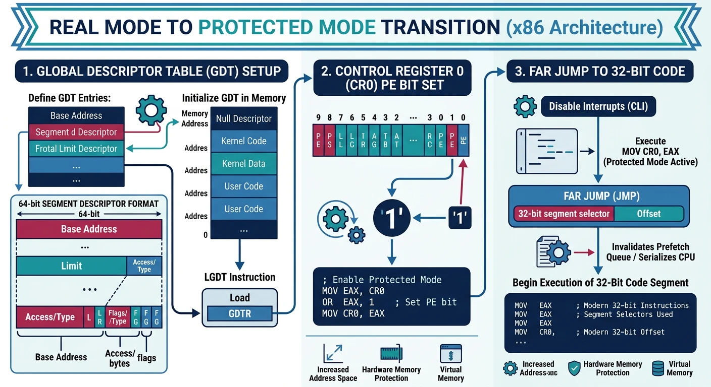
Protected mode gives us 32-bit addressing, memory protection, and paging. The key is setting up a Global Descriptor Table (GDT).
Figure: Protected mode entry – load GDT, enable PE bit in CR0, then far jump to flush the pipeline and enter 32-bit execution.
GDT Layout for Mini OS:
┌─────────┬─────────┬─────────┬──────────┐
│  NULL   │  Code   │  Data   │  Limit   │
│  (0x00) │  (0x08) │  (0x10) │          │
└─────────┴─────────┴─────────┴──────────┘

Segment selectors: Code = 0x08, Data = 0x10
; loader.asm - Stage 2: Protected mode entry
[BITS 16]
[ORG 0x7E00]

loader_start:
    ; Print entering protected mode message
    mov si, msg_pm
    call print_string_16

    ; Enable A20 line (fast method)
    in al, 0x92
    or al, 2
    out 0x92, al

    ; Load GDT
    cli
    lgdt [gdt_descriptor]

    ; Set PE (Protection Enable) bit in CR0
    mov eax, cr0
    or eax, 1
    mov cr0, eax

    ; Far jump to flush pipeline and enter 32-bit code
    jmp 0x08:protected_mode

print_string_16:
    mov ah, 0x0E
.loop:
    lodsb
    test al, al
    jz .done
    int 0x10
    jmp .loop
.done:
    ret

msg_pm: db "Entering protected mode...", 13, 10, 0

; ===== GDT =====
align 8
gdt_start:
    ; NULL descriptor (required)
    dq 0

    ; Code segment: base=0, limit=4GB, 32-bit, ring 0
gdt_code:
    dw 0xFFFF       ; Limit low (0-15)
    dw 0x0000       ; Base low (0-15)
    db 0x00         ; Base middle (16-23)
    db 10011010b    ; Access: Present, Ring 0, Code, Executable, Readable
    db 11001111b    ; Flags: 4KB granularity, 32-bit + Limit high (16-19)
    db 0x00         ; Base high (24-31)

    ; Data segment: base=0, limit=4GB, 32-bit, ring 0
gdt_data:
    dw 0xFFFF       ; Limit low
    dw 0x0000       ; Base low
    db 0x00         ; Base middle
    db 10010010b    ; Access: Present, Ring 0, Data, Writable
    db 11001111b    ; Flags: 4KB granularity, 32-bit + Limit high
    db 0x00         ; Base high
gdt_end:

gdt_descriptor:
    dw gdt_end - gdt_start - 1  ; Size - 1
    dd gdt_start                 ; Address

; ===== 32-bit Protected Mode =====
[BITS 32]
protected_mode:
    ; Setup segment registers
    mov ax, 0x10        ; Data segment selector
    mov ds, ax
    mov es, ax
    mov fs, ax
    mov gs, ax
    mov ss, ax
    mov esp, 0x90000    ; Stack below 1MB

    ; Clear screen
    call clear_screen_32

    ; Print welcome message
    mov esi, msg_welcome
    mov edi, 0xB8000    ; VGA buffer
    mov ah, 0x0F        ; White on black
    call print_string_32

    ; Jump to kernel
    jmp 0x10000         ; Kernel loaded here

clear_screen_32:
    mov edi, 0xB8000
    mov ecx, 80*25
    mov ax, 0x0720      ; Space, gray on black
    rep stosw
    ret

print_string_32:
.loop:
    lodsb
    test al, al
    jz .done
    stosw
    jmp .loop
.done:
    ret

msg_welcome: db "Welcome to Mini OS [32-bit Protected Mode]", 0

times 2048 - ($ - $$) db 0  ; Pad to 4 sectors
Stage 3: Interrupt Handling
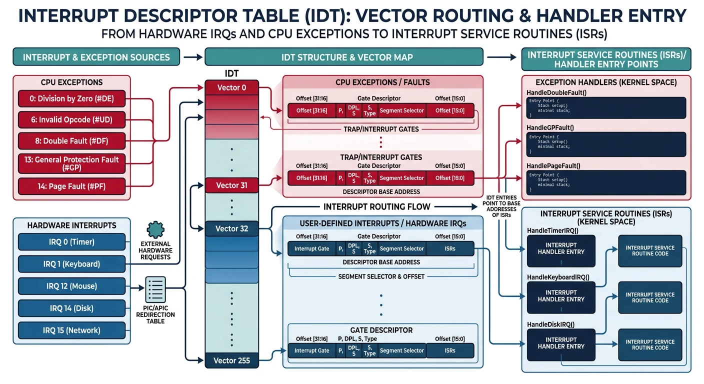
The Interrupt Descriptor Table (IDT) tells the CPU where to jump when interrupts occur—hardware events (keyboard, timer) and software exceptions (divide by zero, page fault).
Figure: IDT interrupt routing – 256 entries map hardware IRQs (timer, keyboard) and CPU exceptions (page fault, GPF) to handler addresses.
; idt.asm - Interrupt Descriptor Table setup
[BITS 32]

section .data

; IDT - 256 entries * 8 bytes = 2048 bytes
align 8
idt_start:
    times 256 dq 0      ; Initialize to zero
idt_end:

idt_descriptor:
    dw idt_end - idt_start - 1
    dd idt_start

; ISR stubs array for easy lookup
isr_stubs:
    dd isr0, isr1, isr2, isr3, isr4, isr5, isr6, isr7
    dd isr8, isr9, isr10, isr11, isr12, isr13, isr14, isr15
    dd isr16, isr17, isr18, isr19, isr20, isr21, isr22, isr23
    dd isr24, isr25, isr26, isr27, isr28, isr29, isr30, isr31
    dd irq0, irq1       ; Hardware interrupts 32-33

section .text

; Setup one IDT entry
; EAX = interrupt number, EBX = handler address
set_idt_entry:
    push edi
    mov edi, idt_start
    shl eax, 3          ; * 8 bytes per entry
    add edi, eax

    mov word [edi], bx      ; Offset low
    mov word [edi+2], 0x08  ; Code segment selector
    mov byte [edi+4], 0x00  ; Reserved
    mov byte [edi+5], 0x8E  ; Type: 32-bit interrupt gate, ring 0, present
    shr ebx, 16
    mov word [edi+6], bx    ; Offset high

    pop edi
    ret

; Initialize IDT with all ISR handlers
idt_init:
    ; Setup exception handlers (0-31)
    xor eax, eax
.setup_loop:
    push eax
    mov ebx, [isr_stubs + eax*4]
    call set_idt_entry
    pop eax
    inc eax
    cmp eax, 34         ; 0-31 exceptions + IRQ 0-1
    jl .setup_loop

    ; Remap PIC (8259) - move IRQs to 32-47
    call pic_remap

    ; Load IDT
    lidt [idt_descriptor]
    sti                 ; Enable interrupts
    ret

; Remap PIC to avoid conflicts with CPU exceptions
pic_remap:
    ; ICW1: Initialize
    mov al, 0x11
    out 0x20, al        ; Master PIC
    out 0xA0, al        ; Slave PIC

    ; ICW2: Vector offset
    mov al, 0x20        ; Master: IRQ 0-7 -> INT 32-39
    out 0x21, al
    mov al, 0x28        ; Slave: IRQ 8-15 -> INT 40-47
    out 0xA1, al

    ; ICW3: Cascade
    mov al, 0x04        ; Master: Slave on IRQ2
    out 0x21, al
    mov al, 0x02        ; Slave: Cascade identity
    out 0xA1, al

    ; ICW4: 8086 mode
    mov al, 0x01
    out 0x21, al
    out 0xA1, al

    ; Mask all interrupts except keyboard (IRQ1)
    mov al, 0xFD        ; 11111101 - only IRQ1 enabled
    out 0x21, al
    mov al, 0xFF        ; Disable all slave IRQs
    out 0xA1, al

    ret

; Macro to generate ISR stub (no error code)
%macro ISR_NOERRCODE 1
isr%1:
    push dword 0        ; Dummy error code
    push dword %1       ; Interrupt number
    jmp isr_common
%endmacro

; Macro for ISR with error code
%macro ISR_ERRCODE 1
isr%1:
    push dword %1       ; CPU already pushed error code
    jmp isr_common
%endmacro

; Generate ISR stubs
ISR_NOERRCODE 0     ; Divide Error
ISR_NOERRCODE 1     ; Debug
ISR_NOERRCODE 2     ; NMI
ISR_NOERRCODE 3     ; Breakpoint
ISR_NOERRCODE 4     ; Overflow
ISR_NOERRCODE 5     ; Bound Range
ISR_NOERRCODE 6     ; Invalid Opcode
ISR_NOERRCODE 7     ; Device Not Available
ISR_ERRCODE   8     ; Double Fault
ISR_NOERRCODE 9     ; Coprocessor Segment
ISR_ERRCODE   10    ; Invalid TSS
ISR_ERRCODE   11    ; Segment Not Present
ISR_ERRCODE   12    ; Stack Segment Fault
ISR_ERRCODE   13    ; General Protection Fault
ISR_ERRCODE   14    ; Page Fault
ISR_NOERRCODE 15    ; Reserved
ISR_NOERRCODE 16    ; x87 FPU Error
ISR_ERRCODE   17    ; Alignment Check
ISR_NOERRCODE 18    ; Machine Check
ISR_NOERRCODE 19    ; SIMD Exception
%assign i 20
%rep 12
ISR_NOERRCODE i
%assign i i+1
%endrep

; Common ISR handler
isr_common:
    pusha               ; Save all registers
    push ds
    push es
    push fs
    push gs

    mov ax, 0x10        ; Kernel data segment
    mov ds, ax
    mov es, ax
    mov fs, ax
    mov gs, ax

    ; Call C handler: void isr_handler(registers_t* regs)
    push esp            ; Pointer to register struct
    extern isr_handler
    call isr_handler
    add esp, 4

    pop gs
    pop fs
    pop es
    pop ds
    popa
    add esp, 8          ; Pop error code and interrupt number
    iret

; IRQ handlers
irq0:                   ; Timer
    push dword 0
    push dword 32
    jmp irq_common

irq1:                   ; Keyboard
    push dword 0
    push dword 33
    jmp irq_common

irq_common:
    pusha
    push ds
    push es
    push fs
    push gs

    mov ax, 0x10
    mov ds, ax
    mov es, ax

    push esp
    extern irq_handler
    call irq_handler
    add esp, 4

    ; Send EOI to PIC
    mov al, 0x20
    out 0x20, al

    pop gs
    pop fs
    pop es
    pop ds
    popa
    add esp, 8
    iret
Stage 4: Keyboard Driver
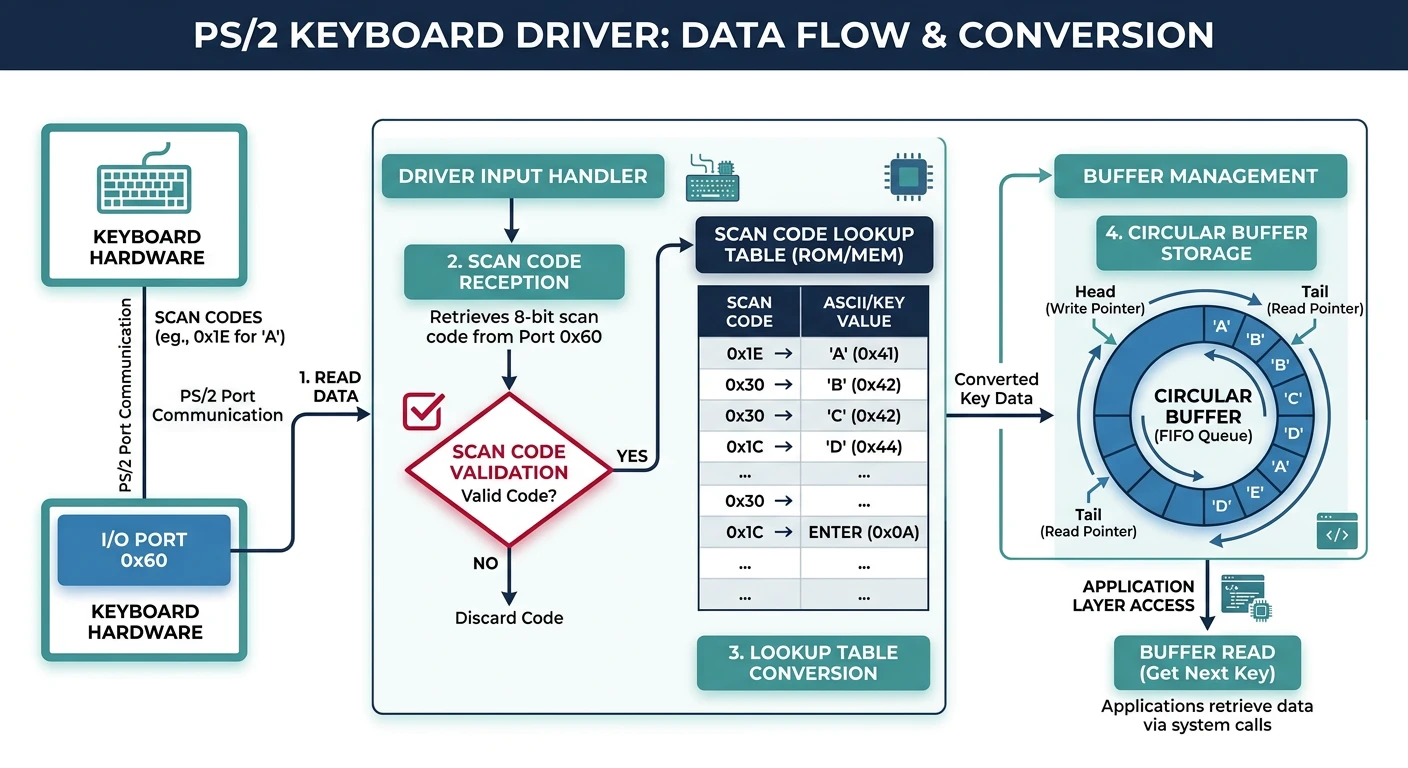
The PS/2 keyboard sends scan codes to port 0x60. We need to convert these to ASCII characters for our shell.
Figure: Keyboard driver pipeline – scan codes from port 0x60 are converted to ASCII via lookup table and stored in a circular key buffer.
; keyboard.asm - PS/2 keyboard driver
[BITS 32]

section .data

; Keyboard buffer (circular)
KEY_BUFFER_SIZE equ 256
key_buffer:     times KEY_BUFFER_SIZE db 0
key_head:       dd 0
key_tail:       dd 0

; Scan code to ASCII lookup table (US QWERTY)
; Index = scan code, value = ASCII (0 = no mapping)
scancode_table:
    ;  0    1    2    3    4    5    6    7    8    9    A    B    C    D    E    F
    db 0,   27,  '1', '2', '3', '4', '5', '6', '7', '8', '9', '0', '-', '=', 8,   9    ; 0x00-0x0F
    db 'q', 'w', 'e', 'r', 't', 'y', 'u', 'i', 'o', 'p', '[', ']', 13,  0,   'a', 's' ; 0x10-0x1F
    db 'd', 'f', 'g', 'h', 'j', 'k', 'l', ';', "'", '`', 0,   '\', 'z', 'x', 'c', 'v' ; 0x20-0x2F
    db 'b', 'n', 'm', ',', '.', '/', 0,   '*', 0,   ' ', 0,   0,   0,   0,   0,   0   ; 0x30-0x3F

; Shift key scan code to ASCII
scancode_shift:
    db 0,   27,  '!', '@', '#', '$', '%', '^', '&', '*', '(', ')', '_', '+', 8,   9
    db 'Q', 'W', 'E', 'R', 'T', 'Y', 'U', 'I', 'O', 'P', '{', '}', 13,  0,   'A', 'S'
    db 'D', 'F', 'G', 'H', 'J', 'K', 'L', ':', '"', '~', 0,   '|', 'Z', 'X', 'C', 'V'
    db 'B', 'N', 'M', '<', '>', '?', 0,   '*', 0,   ' ', 0,   0,   0,   0,   0,   0

shift_pressed:  db 0

section .text

; Keyboard IRQ handler (IRQ1 = INT 33)
global keyboard_handler
keyboard_handler:
    push eax
    push ebx
    push esi

    ; Read scan code from keyboard controller
    in al, 0x60

    ; Check for key release (bit 7 set)
    test al, 0x80
    jnz .key_release

    ; Key press
    ; Check for shift key (scan codes 0x2A, 0x36)
    cmp al, 0x2A
    je .shift_press
    cmp al, 0x36
    je .shift_press

    ; Convert scan code to ASCII
    movzx ebx, al
    cmp byte [shift_pressed], 0
    jnz .use_shift
    mov al, [scancode_table + ebx]
    jmp .check_valid
.use_shift:
    mov al, [scancode_shift + ebx]

.check_valid:
    test al, al             ; Check if valid character
    jz .done

    ; Add to circular buffer
    mov esi, [key_head]
    mov [key_buffer + esi], al
    inc esi
    and esi, KEY_BUFFER_SIZE - 1  ; Wrap around
    mov [key_head], esi
    jmp .done

.shift_press:
    mov byte [shift_pressed], 1
    jmp .done

.key_release:
    ; Check for shift release
    and al, 0x7F            ; Clear release bit
    cmp al, 0x2A
    je .shift_release
    cmp al, 0x36
    je .shift_release
    jmp .done

.shift_release:
    mov byte [shift_pressed], 0

.done:
    pop esi
    pop ebx
    pop eax
    ret

; Read character from keyboard buffer
; Returns: AL = character, or 0 if buffer empty
global kbd_getchar
kbd_getchar:
    mov eax, [key_tail]
    cmp eax, [key_head]     ; Check if buffer empty
    je .empty

    movzx eax, byte [key_buffer + eax]
    mov ebx, [key_tail]
    inc ebx
    and ebx, KEY_BUFFER_SIZE - 1
    mov [key_tail], ebx
    ret

.empty:
    xor eax, eax
    ret

; Wait for and return a character
global kbd_getchar_blocking
kbd_getchar_blocking:
    call kbd_getchar
    test al, al
    jz kbd_getchar_blocking ; Busy wait
    ret
Note: This is a simple polling/interrupt driver. Production drivers handle extended scan codes (0xE0 prefix), caps lock, and multiple keyboard layouts.
Stage 5: VGA Text Output
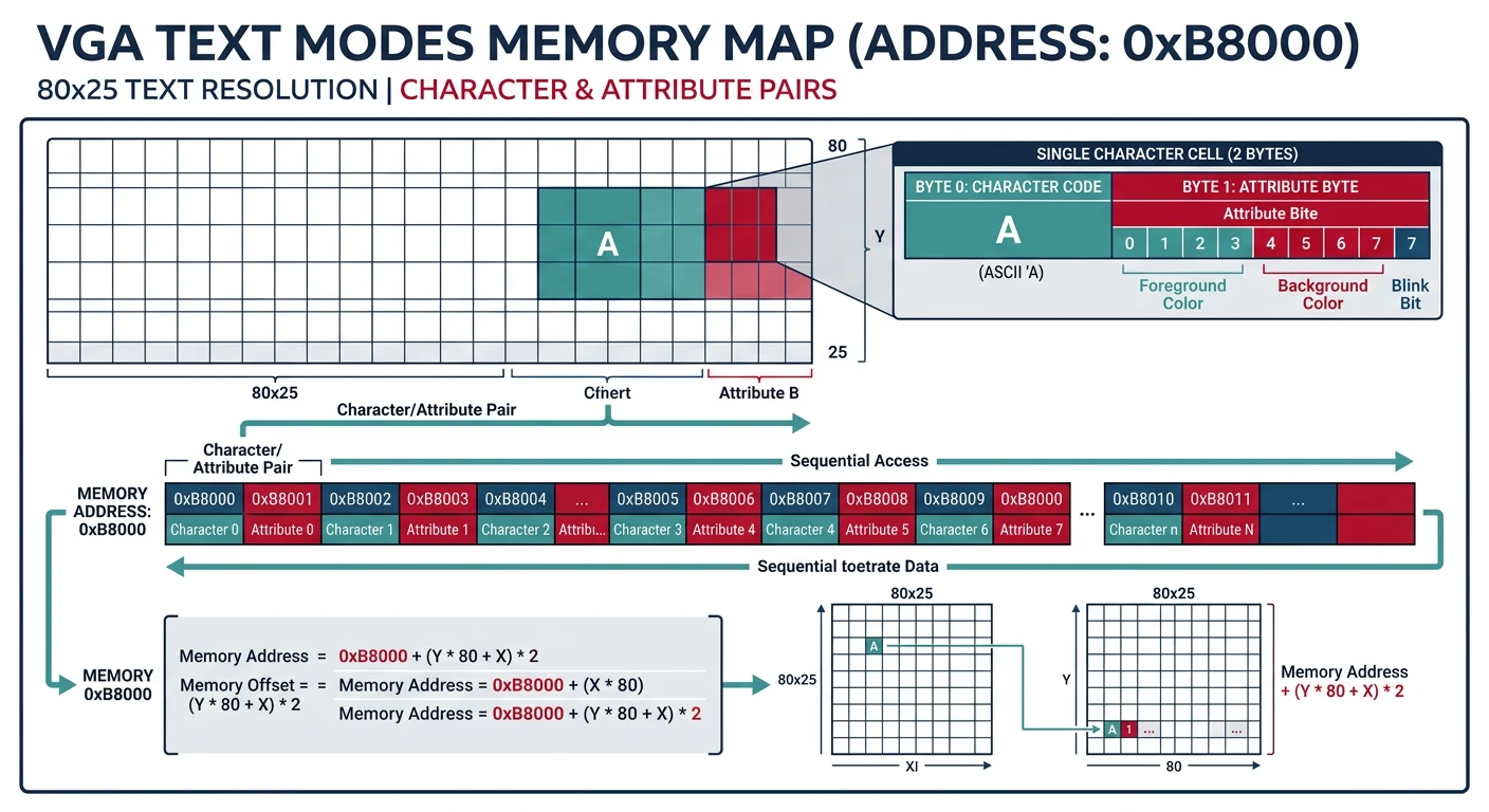
VGA text mode uses a memory-mapped buffer at 0xB8000. Each character is 2 bytes: ASCII + attribute (color).
Figure: VGA text mode layout – each screen cell at 0xB8000 stores a character byte and attribute byte (foreground/background color) in an 80×25 grid.