x86 Assembly Series Part 19: Bootloader Development
February 6, 2026Wasil Zafar40 min read
Master bootloader development: BIOS boot process, MBR structure, real mode assembly, disk I/O with BIOS interrupts, loading a kernel, and transitioning to protected/long mode.
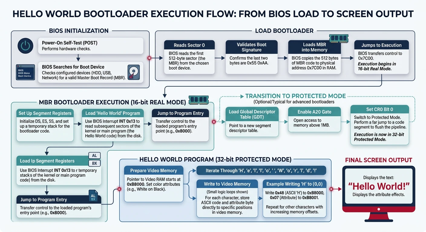
Hello world bootloader: BIOS loads MBR at 0x7C00, code prints via INT 10h, then halts
[BITS 16]                   ; 16-bit real mode
[ORG 0x7C00]                ; BIOS loads us here

start:
    ; Set up segment registers
    xor ax, ax
    mov ds, ax
    mov es, ax
    mov ss, ax
    mov sp, 0x7C00          ; Stack below bootloader

    ; Print "Hello"
    mov si, message
    call print_string

    ; Halt
    cli                     ; Disable interrupts
    hlt                     ; Halt CPU

print_string:
    mov ah, 0x0E            ; BIOS teletype function
.loop:
    lodsb                   ; Load byte from SI into AL
    test al, al             ; Check for null terminator
    jz .done
    int 0x10                ; BIOS video interrupt
    jmp .loop
.done:
    ret

message: db "Hello from bootloader!", 0

; Pad to 510 bytes and add boot signature
times 510 - ($ - $$) db 0
dw 0xAA55                   ; Boot signature
# Assemble and test
nasm -f bin boot.asm -o boot.bin
qemu-system-x86_64 -drive format=raw,file=boot.bin
BIOS Interrupts
INT 10h (Video Services)
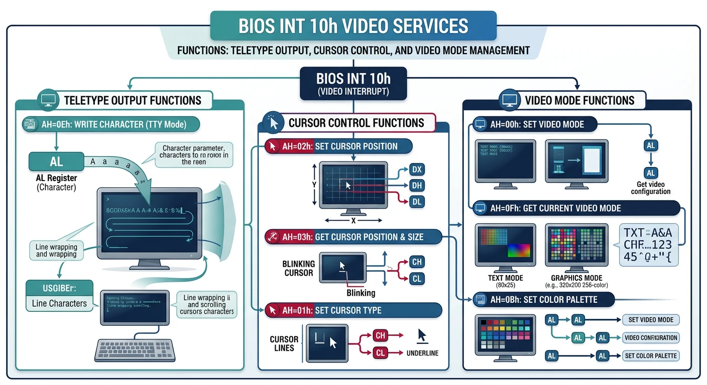
INT 10h provides BIOS video services—your interface to the screen before any OS is loaded.
BIOS INT 10h video services: teletype output (AH=0Eh), cursor positioning, and video mode switching
AH
Function
Parameters
Returns
0x00
Set Video Mode
AL = mode (0x03=text, 0x13=VGA)
-
0x02
Set Cursor Position
BH=page, DH=row, DL=col
-
0x03
Get Cursor Position
BH=page
DH=row, DL=col
0x0E
Teletype Output
AL=char, BL=color
-
0x13
Write String
ES:BP=string, CX=len, DH/DL=pos
-
; Video services examples
bits 16
org 0x7C00

; Set 80x25 text mode
mov ah, 0x00
mov al, 0x03            ; 80x25 color text
int 0x10

; Set cursor to row 5, column 10
mov ah, 0x02
mov bh, 0               ; Page 0
mov dh, 5               ; Row
mov dl, 10              ; Column
int 0x10

; Print character 'A' in light green
mov ah, 0x0E
mov al, 'A'
mov bl, 0x0A            ; Light green
int 0x10

; Print string using INT 10h function 13h
mov ah, 0x13
mov al, 1               ; Mode: update cursor
mov bh, 0               ; Page 0
mov bl, 0x0F            ; White on black
mov cx, msg_len         ; String length
mov dh, 10              ; Row 10
mov dl, 20              ; Column 20
mov bp, message         ; ES:BP = string
int 0x10

message: db "Boot OK!"
msg_len equ $ - message
INT 13h (Disk Services)
INT 13h is the BIOS disk interface. Use it to load your kernel from disk into memory.
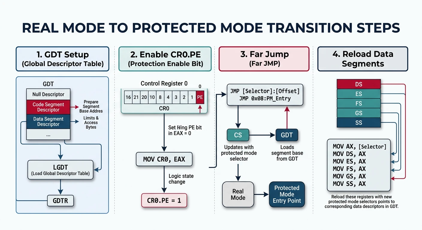
Transitioning from real mode to protected/long mode is the bootloader's most critical task. Here's the complete sequence:
Real → Protected mode transition: CLI, load GDT, set CR0.PE, far jump to flush pipeline, reload segments
x86 CPU Mode Transitions
stateDiagram-v2
    [*] --> RealMode
    RealMode --> ProtectedMode : Set PE bit in CR0
    ProtectedMode --> LongMode : Set LME in EFER + PG in CR0
    ProtectedMode --> RealMode : Clear PE bit (rare)

    state RealMode {
        [*] --> RM16 : 16-bit addressing
        note right of RM16 : 1MB address space\nNo memory protection\nSegment:Offset
    }
    state ProtectedMode {
        [*] --> PM32 : 32-bit addressing
        note right of PM32 : 4GB address space\nGDT + Paging\nPrivilege rings
    }
    state LongMode {
        [*] --> LM64 : 64-bit addressing
        note right of LM64 : 256TB virtual space\n4-level paging\nRIP-relative
    }
Mode Transition Checklist:

☐ 1. Disable interrupts (CLI)
☐ 2. Enable A20 gate (access > 1MB)
☐ 3. Load Global Descriptor Table (LGDT)
☐ 4. Set CR0.PE = 1 (Protected Mode Enable)
☐ 5. Far jump to flush prefetch queue
☐ 6. Reload segment registers with GDT selectors

For 64-bit Long Mode, also:
☐ 7. Enable PAE (CR4.PAE = 1)
☐ 8. Setup 4-level page tables
☐ 9. Load CR3 with PML4 address
☐ 10. Enable Long Mode (EFER.LME = 1)
☐ 11. Enable Paging (CR0.PG = 1)
☐ 12. Far jump to 64-bit code segment
; Complete Real → Protected Mode transition
bits 16

enter_protected_mode:
    cli                     ; 1. Disable interrupts

    ; 2. Enable A20 (keyboard controller method)
    call .wait_ready
    mov al, 0xAD            ; Disable keyboard
    out 0x64, al
    call .wait_ready
    mov al, 0xD0            ; Read output port
    out 0x64, al
    call .wait_data
    in al, 0x60             ; Get current value
    push ax
    call .wait_ready
    mov al, 0xD1            ; Write output port
    out 0x64, al
    call .wait_ready
    pop ax
    or al, 2                ; Set A20 bit
    out 0x60, al
    call .wait_ready
    mov al, 0xAE            ; Enable keyboard
    out 0x64, al
    jmp .a20_done

.wait_ready:
    in al, 0x64
    test al, 2
    jnz .wait_ready
    ret
.wait_data:
    in al, 0x64
    test al, 1
    jz .wait_data
    ret
.a20_done:

    ; 3. Load GDT
    lgdt [gdt_descriptor]

    ; 4. Enable Protected Mode
    mov eax, cr0
    or eax, 1
    mov cr0, eax

    ; 5. Far jump (flushes pipeline, loads CS)
    jmp 0x08:protected_entry

bits 32
protected_entry:
    ; 6. Reload segment registers
    mov ax, 0x10            ; Data segment selector
    mov ds, ax
    mov es, ax
    mov fs, ax
    mov gs, ax
    mov ss, ax
    mov esp, 0x90000        ; Stack in free memory

    ; Now in 32-bit Protected Mode!
    ; Continue to long mode setup or jump to kernel...
    jmp pm_kernel_entry

; GDT for Protected Mode
align 8
gdt_start:
    dq 0                    ; Null descriptor
gdt_code:
    dw 0xFFFF, 0x0000       ; Limit, Base 0:15
    db 0x00                 ; Base 16:23
    db 10011010b            ; Access: Code, readable
    db 11001111b            ; Flags + Limit 16:19
    db 0x00                 ; Base 24:31
gdt_data:
    dw 0xFFFF, 0x0000
    db 0x00
    db 10010010b            ; Access: Data, writable
    db 11001111b
    db 0x00
gdt_end:

gdt_descriptor:
    dw gdt_end - gdt_start - 1  ; Size - 1
    dd gdt_start                ; Address
Critical: The far jump after setting CR0.PE is mandatory! It flushes the CPU's instruction prefetch queue, which may contain real-mode decoded instructions.
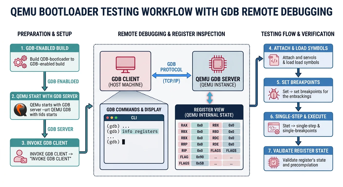
Testing with QEMU
QEMU is essential for bootloader development. It provides fast iteration and powerful debugging capabilities.
QEMU + GDB bootloader debugging workflow: assemble, run with -s -S, connect GDB, step through boot code
Basic Usage
# Build and run bootloader
nasm -f bin bootloader.asm -o boot.bin

# Run in QEMU (legacy BIOS)
qemu-system-x86_64 -drive format=raw,file=boot.bin

# Create proper disk image with kernel
cat boot.bin kernel.bin > os.img
# Pad to floppy size (optional)
truncate -s 1440k os.img
qemu-system-x86_64 -fda os.img

# Hard disk emulation
qemu-system-x86_64 -hda os.img
Debugging with GDB
# Start QEMU paused, waiting for GDB connection
qemu-system-x86_64 -drive format=raw,file=boot.bin -s -S

# In another terminal, connect GDB
gdb -ex "target remote :1234" \
    -ex "set architecture i8086" \
    -ex "break *0x7c00" \
    -ex "continue"

# Useful GDB commands for bootloader debugging:
(gdb) x/10i $pc           # Disassemble at current position
(gdb) info registers      # Show all registers
(gdb) x/16xb 0x7c00       # Examine memory (hex bytes)
(gdb) stepi               # Step one instruction
(gdb) nexti               # Step over (skip calls)
(gdb) break *0x7c20       # Breakpoint at address
QEMU Options Reference
Option
Description
-s
Start GDB server on port 1234
-S
Pause CPU at startup (wait for GDB)
-d int
Log interrupts to console
-d cpu,exec
Log CPU state and executed blocks
-D qemu.log
Write debug output to file
-nographic
Disable graphical output, use serial
-serial mon:stdio
Redirect serial to terminal
-m 512M
Set RAM size to 512MB
-monitor stdio
QEMU monitor in terminal
QEMU Monitor Commands
# Press Ctrl+Alt+2 in QEMU window for monitor, or use -monitor stdio
(qemu) info registers     # Show CPU registers
(qemu) info mem           # Show memory mappings
(qemu) xp /10i 0x7c00     # Disassemble memory
(qemu) x /16xb 0x7c00     # Examine memory
(qemu) gdbserver          # Enable GDB server
(qemu) stop               # Pause emulation
(qemu) cont               # Continue emulation
(qemu) q                  # Quit QEMU
Exercise
Debug Your Bootloader
Create a bootloader that prints "Hello" and loops
Start QEMU with -s -S
Connect GDB, set breakpoint at 0x7C00
Step through each instruction
Examine the boot signature at 0x7DFE (x/2xb 0x7dfe)